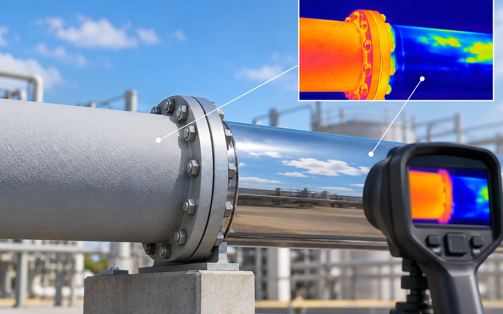
A thermal camera receives radiation emitted by the target and reflected from its surroundings. Emissivity affects how that signal becomes a temperature estimate, so two surfaces at the same temperature can appear different. Interpretation depends on the surface, viewing conditions and measurement settings.
Table of Contents
Why can equal temperatures look different?
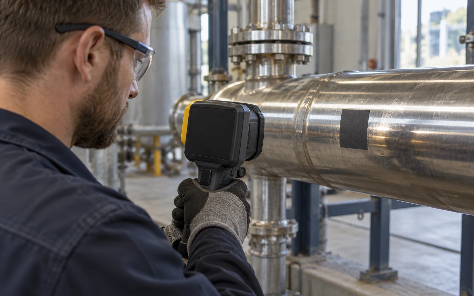
A surface with low emissivity can reflect a substantial part of the radiation seen by the camera. Polished metal may therefore appear cold beneath an open sky or warm near another hot object, even when its own temperature has not changed in the way the image suggests.
The FLIR measurement guidance identifies emissivity, reflected temperature, distance and atmospheric conditions as relevant inputs. It also warns about reflections and resolution limits. Those principles inform inspection design; the settings available on a particular airborne camera still need to be verified.
Do not assign emissivity from a material name alone. Paint, corrosion, oxidation, surface finish, wetness and the measurement band can matter. A visible photograph documenting surface condition is often more useful than an unexplained preset.
What is different about reflected apparent temperature?
Reflected apparent temperature represents radiation from the surrounding scene reflected toward the camera. It is not automatically the same as the air temperature read by a weather sensor.
A drone changes viewing angle and position during a pass. The reflected scene can change with it. A patch that appears to move or change intensity with view direction deserves investigation before a maintenance ticket attributes it to internal heating.
Where the approved inspection method allows a repeat view, keep the target identity fixed and vary the view deliberately. Record time, operating load and environmental change so that a real change in the asset is not mistaken for a reflection test result.
An evidence matrix for thermal findings
Separate the confidence of observation from the confidence of diagnosis. The following matrix is a reporting aid, not a temperature acceptance standard.
| Observation | Alternative explanation | Evidence to retain | Appropriate report wording |
|---|---|---|---|
| Hot-looking patch on polished metal | Reflected warm surroundings | Visible surface image and changed view | Apparent anomaly requiring confirmation |
| Similar pattern in repeat views | Persistent surface-temperature difference | Radiometric files and operating conditions | Repeatable thermal pattern |
| Tiny bright feature at long distance | Mixed pixels or unresolved target | Target size, lens and range | Temperature may be spatially diluted |
| Different colors on two inspections | Different palette or display range | Original data and common scale | Compare measurements, not screenshots |
| Anomaly coincides with load change | Real operating-state difference | Load and timestamp records | Condition-specific observation |
Avoid comparing a maximum pixel in one image with a region average in another. Use the same measurement definition and explain excluded pixels or background contamination.
How should radiometric data be captured?
Retain original radiometric files when the camera and workflow support them. A compressed screenshot usually preserves the displayed pattern but may not preserve the information needed to revise measurement assumptions.
Record camera and lens, calibration status available from the supplier, focus, range, emissivity assumption, reflected apparent temperature basis, atmospheric settings and asset operating state. Link each file to a stable asset ID. Confirm that the target occupies enough of the sensor for the intended measurement according to the camera’s measurement specification.
Do not apply reference tape, touch equipment or alter a live asset merely to improve a measurement. Any reference-surface procedure belongs within the asset owner’s approved inspection method and access controls.
Turn anomalies into useful inspection work
Report three separate outputs: where the observation is, what the image supports, and what would resolve the remaining uncertainty. Temperature precision on a display should not imply that the surface properties and measurement geometry are known equally well.
The solar panel inspection workflow connects thermal observations with asset IDs and follow-up actions. For oil and gas facilities, thermal evidence also needs the process state and inspection purpose.
Retain the radiometric export with the emissivity setting, reflected-temperature estimate, viewing conditions and comparison measurements. Those inputs explain how the reported temperature was obtained.
FAQs
Can a bright thermal spot be a reflection?
Yes. Low-emissivity surfaces can reflect radiation from the surroundings. Changes with viewing angle can help investigate a reflection but do not alone prove the cause.
Is ambient air temperature the reflected temperature setting?
Not necessarily. Reflected apparent temperature describes the radiation environment seen by the surface and can differ from air temperature.
Does a color thermal image prove a component fault?
No. Palette and scale settings affect appearance. A fault interpretation needs radiometric context, asset conditions and appropriate corroborating evidence.