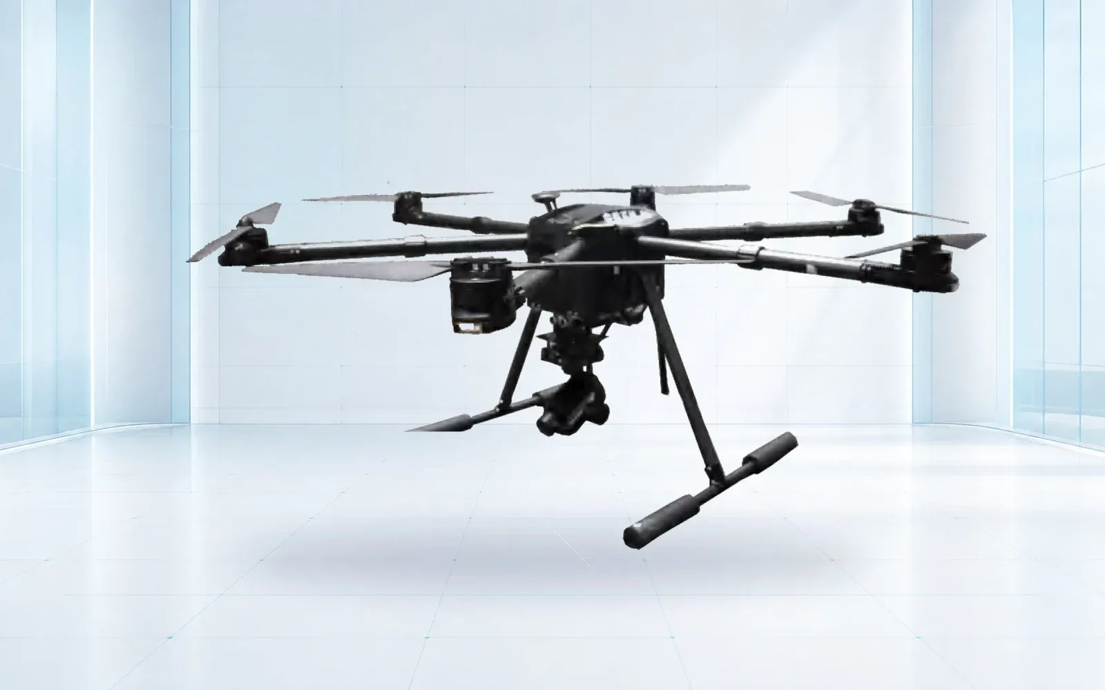
A cell tower drone inspection becomes useful when every image resolves to the correct sector, elevation, antenna, mount, cable route, or structural member—and when the flight team has controlled the site's radio-frequency, aviation, and ground hazards. An attractive 3D model without reliable asset identity is not a maintenance record.
Table of Contents
- 1. Define the Tower Asset and Maintenance Decision
- 2. Build an Antenna and Viewpoint Identity Model
- 3. Plan an RF-Aware Site and Flight Assessment
- 4. Select the Platform and Sensor for Required Evidence
- 5. Preserve Geometry, Scale, and Media Provenance
- 6. Review Findings and Create Traceable Work Orders
- 7. Accept the Workflow on Representative Tower Types
- 8. FAQs
1. Define the Tower Asset and Maintenance Decision
Begin with the tower owner’s asset hierarchy and inspection scope. Identify site, structure, sector or azimuth, elevation, platform or mount, antenna, remote radio, cable run, connector area, structural member, grounding element, and ancillary equipment as applicable. The hierarchy should match the system that receives the result; a new inspection label that cannot map to the owner’s asset register creates reconciliation work.
For each component family, write the condition that imagery can support, the views required, the smallest relevant feature, and the next decision. Useful aerial tasks may include documenting apparent displacement, missing or loose-looking external hardware, cable routing, visible jacket condition, corrosion candidates, nest or foreign-object presence, mount geometry, and change from a prior epoch. Do not use an image to claim torque, electrical performance, internal condition, or RF performance that it did not measure.
| Component or question | Required views | Evidence limit | Follow-up path |
|---|---|---|---|
| Antenna and mount identity | Sector overview, face, side profile | Image does not prove alignment tolerance by itself | Geometry review or survey method |
| Cable and connector route | Continuous contextual sequence and details | Hidden backs and internal seals remain unobserved | Targeted climb or ground test |
| Structural surface candidate | Overview plus perpendicular detail | Surface appearance does not establish section loss | Engineer-defined confirmation |
| Foreign object or vegetation | Context, clearance, and detail | Perspective can distort separation | Site review and safe removal plan |
End the scope with disposition codes: acceptable, monitor, uncertain, requires another method, planned corrective work, or urgent escalation. If the reviewer cannot send a result to a named owner and system, the workflow stops at media collection.
2. Build an Antenna and Viewpoint Identity Model
Communication structures repeat patterns. Three sectors may use similar antennas at similar elevations, and multiple photographs may show overlapping mounts. Use a sector convention tied to surveyed or owner-provided azimuths, not to where the pilot happened to stand. Record elevation or mount level and a stable equipment ID in the mission plan and review interface.
Define required views by component. A sector overview establishes context; a face view supports surface and external-hardware review; a side profile supports orientation and clearance; a rear or oblique view may be needed for brackets, cables, and radios. Where a safe view is impossible, mark it unobserved instead of letting the image count imply completion.
Capture order can reduce identity errors. Move systematically by sector and elevation, use a visible slate or synchronized mission record where appropriate, and run a field check before leaving a level. Filenames alone are weak identifiers because they can be reordered, renamed, or separated from their flight log.
If a model or photogrammetric output is required, define its coordinate system, control, expected accuracy, reflective or repetitive-surface limitations, and how a model feature maps back to original images. A visually complete mesh is not evidence that every antenna face or connection was captured at defect-resolving quality.
3. Plan an RF-Aware Site and Flight Assessment
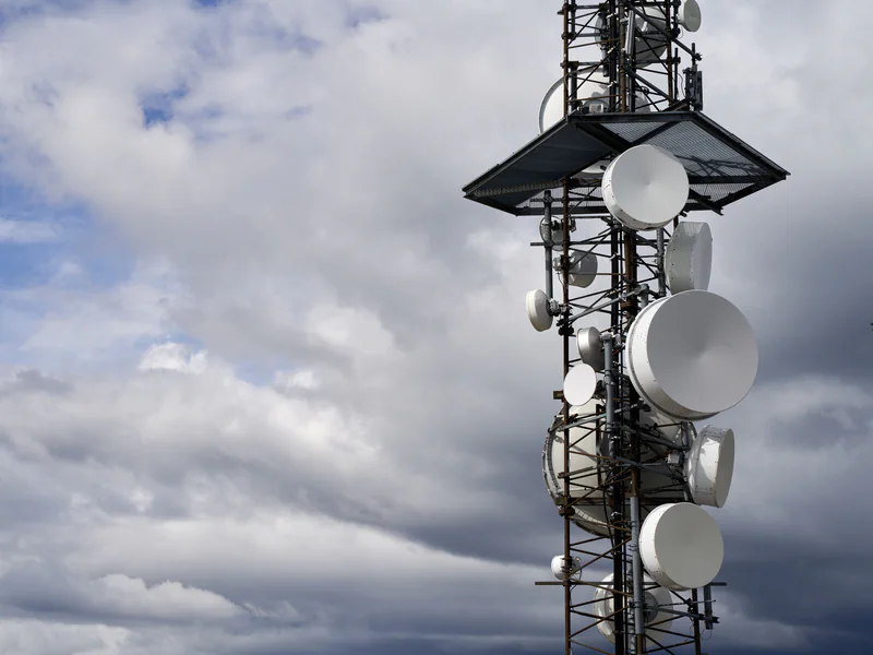
Treat radio-frequency exposure and aircraft behavior as separate questions. RF safety controls protect personnel and depend on source characteristics, duty cycle, access, distance, and site conditions. Aircraft and link performance depend on the installed avionics, command frequencies, payload, shielding, geometry, and local electromagnetic environment. One checklist item cannot close both.
Obtain current site RF information from the owner and define who is authorized to assess or change transmitter status. OSHA’s role of RF measurements explains that measurements and calculations support exposure assessment, while the FCC provides a current radio-frequency safety entry point. These sources do not give a universal drone standoff distance. Use the site’s competent RF process.
Survey the ground area, access, fall-object exposure, climbers or crews, guy wires, temporary rigging, nearby distribution lines, buildings, public roads, and emergency access. Establish who controls the work area and how flight stops if a person, vehicle, climber, or transmitter state changes.
Observe aircraft behavior progressively. Test on the ground, then at conservative positions, while monitoring command link, video, GNSS, compass or heading behavior, and flight-controller alerts. Define an immediate retreat path and do not continue merely because the video appears stable.
4. Select the Platform and Sensor for Required Evidence
Close tower work favors controlled hover, slow translation, predictable braking, and a camera that can hold the required angle without forcing the airframe too close. Broader site documentation or access mapping may use a different platform. Evaluate the aircraft with its actual payload, batteries, antennas, software, and operating reserve.
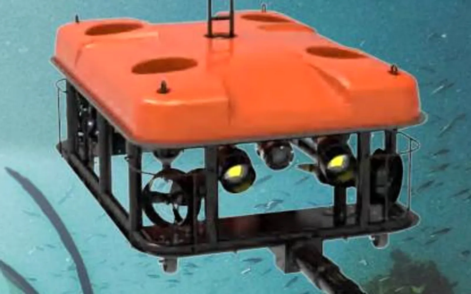
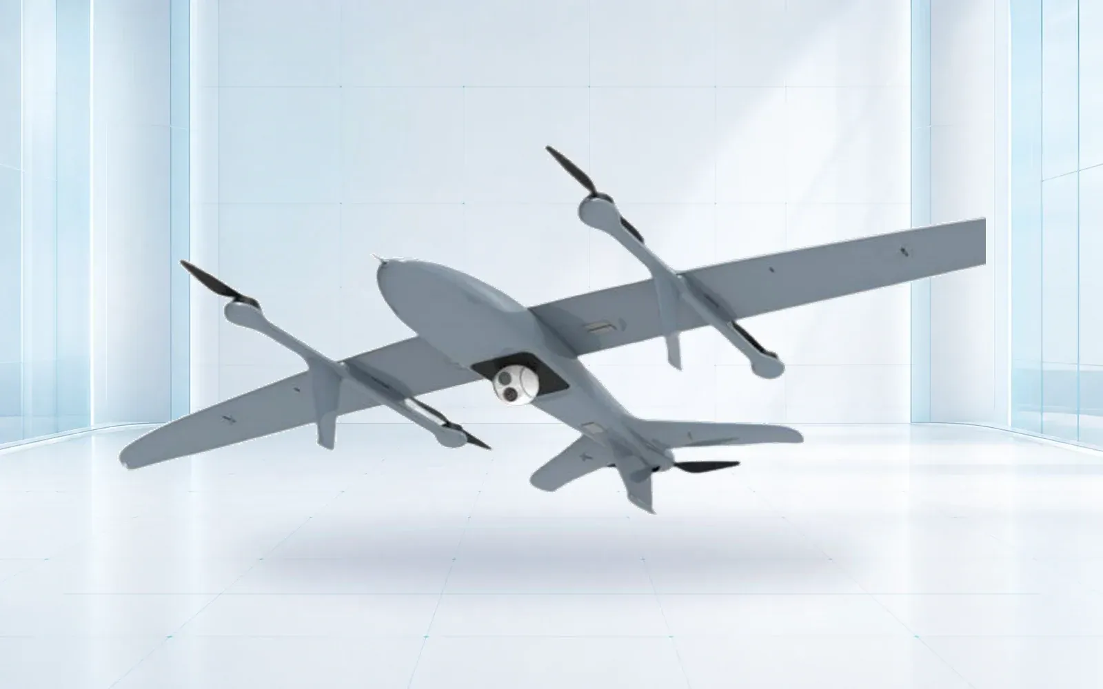
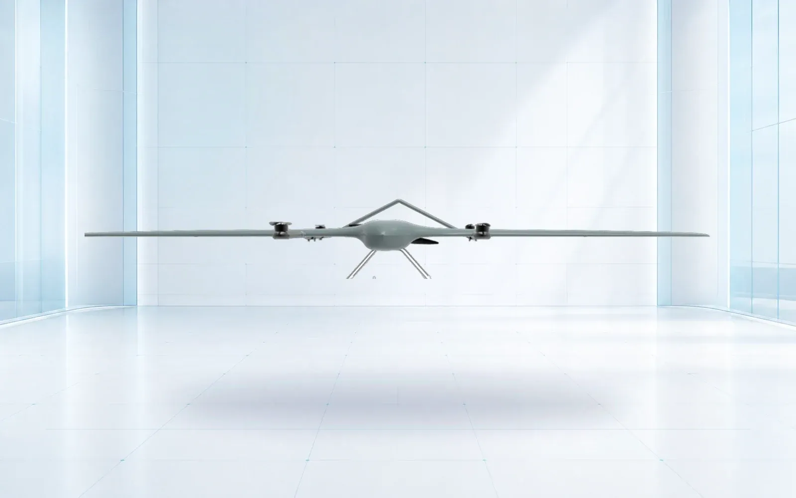
The F4 waterproof multirotor is a reference for close observation where its verified configuration fits the tower environment. The ZJ-G25 VTOL is a reference for wider-area missions. A product page does not establish RF compatibility, evidence resolution, or safe standoff at a particular site; those require engineering review and a representative trial.
Specify visual performance at the component: smallest feature to resolve, target distance, permitted angle, exposure and blur limit, and required contextual view. Optical zoom can support standoff, but narrow fields of view increase identity and coverage risk. Stabilization helps framing but does not remove motion blur or focus failure.
Thermal imaging, where an owner-approved method exists, should retain radiometric originals and the operating context needed for interpretation. A colored image of an antenna or connector is not an RF or electrical diagnosis. Likewise, a point cloud can support geometry but cannot prove fastener torque.
5. Preserve Geometry, Scale, and Media Provenance
At the field quality gate, confirm correct sector and elevation, all required views, sharp target detail, usable exposure, original file integrity, and a clear link to the flight record. Recollect failures while the operational controls are still in place. A later reviewer should not have to guess whether an empty folder means “clean,” “not required,” or “not observed.”
Retain originals and create non-destructive derivatives for annotation or measurement. Record lens parameters, any calibration, model software, processing settings, and control points when geometry is an output. If a measurement is taken from imagery, state the method and uncertainty rather than presenting extra decimal places as accuracy.
Every finding should include site, structure, sector, elevation, component ID, view direction, original media IDs, capture time, reviewer, observed condition, uncertainty, and disposition. Store the field-of-view context next to the detail. A tight crop may be good for discussion but weak for locating the correct component.
The OSHA communication-tower inspection directive emphasizes the specialized hazards of tower work. A drone changes exposure and access for some tasks; it does not remove the owner’s responsibility to coordinate competent personnel, site controls, and any follow-up climb.
6. Review Findings and Create Traceable Work Orders
Separate capture quality review from condition review. The first asks whether the required evidence exists. The second asks what that evidence supports. Use a controlled taxonomy and allow “uncertain” or “alternate method required”; otherwise reviewers may turn ambiguous pixels into false certainty.
Group duplicates across adjacent views but retain the media chain. For each accepted finding, assign the asset ID, condition class, urgency basis, requested follow-up, and owner. A work-order package should make the field location reproducible and include safe access context where the inspection can support it.
Close the record after climb, adjustment, repair, replacement, or a decision to monitor. Link the confirmed outcome back to the original candidate so the next inspection can distinguish recurring, unchanged, and resolved conditions. That dataset is also the appropriate foundation for evaluating automated screening—not unreviewed annotations alone.
The industrial UAV datasheet reality check explains how to convert nominal aircraft claims into mission evidence. Apply the same discipline to tower-specific standoff, image quality, RF behavior, and usable reserve. The critical infrastructure protection solution places aerial inspection within a wider operational and security context.
7. Accept the Workflow on Representative Tower Types
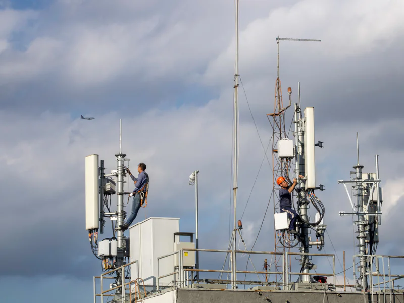
Choose self-supporting, monopole, rooftop, and guyed structures from the actual scope as applicable. Include different sector layouts, elevations, backgrounds, RF states, wind directions, public-access constraints, and known difficult components. Use known targets and clean components to measure both detection and nuisance workload.
Score required-view coverage, asset-ID accuracy, target resolvability, model or measurement uncertainty where claimed, unusable-capture rate, link and navigation behavior, reviewer agreement, time to decision, and work-order handoff. Test missing-view, incorrect-ID, degraded-link, unexpected-person, and change-in-transmitter-state scenarios.
Acceptance should state what the method covers and what still needs climbing or another technique. Set retest triggers for a new camera, lens, aircraft, flight-control release, processing pipeline, tower family, RF environment, or owner taxonomy.
For a representative trial, review the industrial UAV category and technical resources, then contact OMNI UXV with tower types, asset hierarchy, RF controls, required views, target detail, and work-order fields.
8. FAQs
Can a drone inspection replace climbing a cell tower?
A drone can reduce exposure for defined visual and geometric checks, but it cannot automatically replace tactile, torque, electrical, internal, or other work that requires physical access. Each condition needs an approved observation and confirmation method.
Can radio-frequency energy affect a tower inspection drone?
The site RF environment can affect people and may create equipment or link concerns depending on frequency, field strength, separation, and the installed system. The owner and competent RF personnel should define controls from site information and measurements rather than assumptions.
How should antenna assets be identified in inspection media?
Use a stable hierarchy such as site, structure, sector or azimuth, elevation, mount, antenna or radio ID, cable route, and view direction. Preserve that identity with original media and the maintenance record.
What should a cell tower drone acceptance test measure?
Measure required-view coverage, asset-ID accuracy, resolvable detail, geometric uncertainty, unusable captures, link and navigation behavior, RF and ground controls, reviewer agreement, and successful work-order handoff.