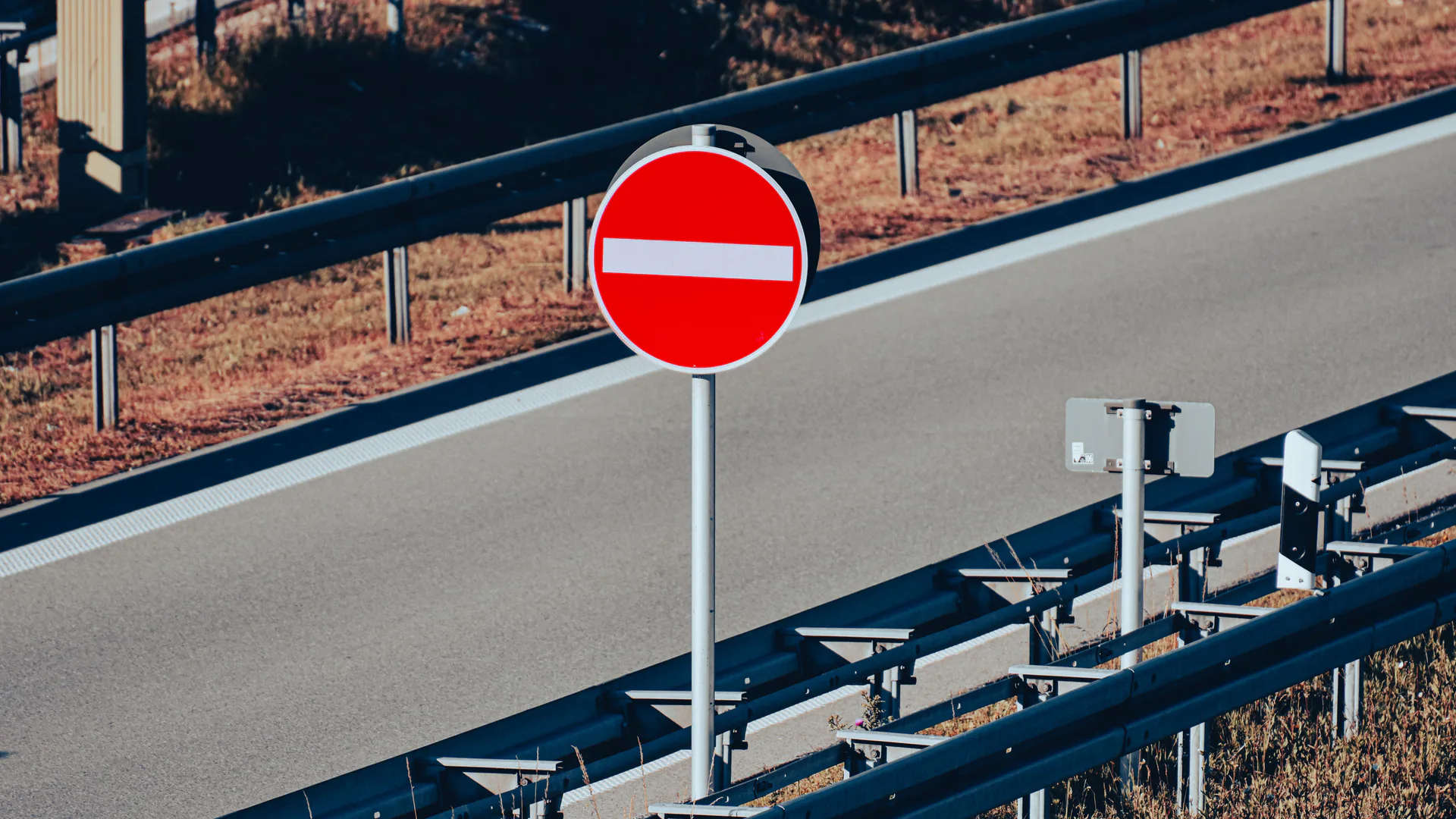
A wrong-way driver detection system must establish direction inside a defined decision zone, warn the driver while correction is still possible, notify operators with enough evidence to act, and avoid turning every unusual movement into a high-consequence alarm. Sensor range matters, but placement, logic, latency, and response ownership determine whether the system works.
Table of Contents
- Define the Decision Zone and Required Action
- Choose Sensor Geometry for Direction, Not Presence Alone
- Separate Detection, Confirmation, and Warning Outputs
- Integrate Signs, Beacons, Operators, and Upstream Messages
- Control Nuisance Alarms and Degraded States
- Preserve Event Evidence and Measure Outcomes
- Run Site Acceptance and Seasonal Retests
- FAQs
Define the Decision Zone and Required Action
Map the ramp or roadway from the first plausible wrong entry to the point at which the vehicle reaches higher-speed opposing traffic. Identify signs, gore, channelization, intersections, driveways, shoulders, maintenance access, sight distance, lighting, power, communications, and safe equipment locations. Do not begin with a generic sensor radius.
Divide the route into functional zones. An entry or decision zone establishes that a vehicle has crossed a boundary in the wrong direction. A correction zone is where local signs or beacons may still influence the driver. A verification zone confirms continuation. An upstream-response zone supports operator, law-enforcement, traffic-management, or road-user messages.
The FHWA Wrong-Way Driving Detection System noteworthy practice and its Wrong-Way Driving Compendium provide public-agency context for active detection and warning. Use such deployments as design evidence, but validate the geometry and operating plan for the actual ramp.
| Zone | Required decision | Typical output | Acceptance measure |
|---|---|---|---|
| Entry or decision | Did a tracked vehicle cross in the prohibited direction? | Candidate event | Direction and lane accuracy at the decision line |
| Correction | Is the candidate credible enough to warn locally? | Sign, beacon, or local warning where approved | Trigger latency and visibility |
| Verification | Did the vehicle continue, stop, or self-correct? | Confirm, update, or clear event | Track continuity and state-change accuracy |
| Upstream response | What should operators and road users do? | Operator alarm, agency interface, message workflow | Delivery, acknowledgment, and response time |
Define authority for every output. The system may activate an approved field device, notify a traffic management center, share evidence, or request a law-enforcement response. It should not invent road-control or enforcement authority.
Choose Sensor Geometry for Direction, Not Presence Alone
Presence detection is insufficient. The system must observe a trajectory across at least two meaningful positions, infer direction in the road coordinate system, assign the correct lane or ramp, and handle stops, U-turns, and self-correction. Sensor placement should maximize this trajectory while avoiding occlusion and adjacent-road contamination.
Radar can provide range, speed, angle, and tracks under varied lighting when installed and configured appropriately. Video can provide lane context, vehicle class, visible confirmation, and evidence, but it faces glare, darkness, precipitation, lens contamination, headlight bloom, shadows, and occlusion. Fusion should combine complementary evidence rather than allow one weak source to inherit the other’s confidence.
Survey mounting height, yaw, pitch, road grade, curvature, barriers, sign structures, vegetation, queues, lane widths, and large-vehicle occlusion. A long datasheet range does not guarantee that a sensor can distinguish the prohibited movement from an authorized turn or adjacent roadway at the decision line.
The TRVF-8221 radar-video fusion sensor is a reference building block for multi-lane tracks and event data. It is not described here as an accepted wrong-way system without site-specific logic and testing. Require raw or inspectable tracks, detection zones, direction state, quality flags, and camera association—not only a red alarm icon.

Separate Detection, Confirmation, and Warning Outputs
Use an event state machine. A track may enter as a candidate, become direction-confirmed after crossing the decision line, trigger local warning, progress to continued wrong-way travel, self-correct, stop, leave the coverage area, become uncertain, or clear. Define timeouts and transitions for each state.
Local warning should occur early enough to be useful but not so early that normal turning paths activate it. Place and design signs and beacons within the road authority’s approved traffic-control plan. The current U.S. national standard is the MUTCD 11th Edition, Revision 1, effective March 5, 2026; project designers must use the applicable edition, state adoption, and agency approval rather than copying a vendor rendering.
Operator alarms should include site, ramp, direction, event state, current position or zone, time, supporting image or clip where authorized, sensor health, and recommended response from the approved plan. Avoid language that claims intent. The system observes a track consistent with prohibited movement; it does not know why the driver entered.
The TRVF-8221-SW1 approaching-vehicle warning unit is a reference for integrating detection with warning logic at constrained road locations. Its use in a wrong-way design requires validated direction logic, approved field devices, site configuration, and agency acceptance.
Integrate Signs, Beacons, Operators, and Upstream Messages
Build an interface matrix for local signs or beacons, traffic management center, incident platform, CCTV or video management, dynamic message signs, law-enforcement notification, maintenance, and event archive. For every interface, define message fields, timing, acknowledgment, retry, degraded behavior, cybersecurity, and ownership.
Local warnings and upstream messages serve different audiences. A wrong-way driver may need an immediate, unambiguous correction cue. Correct-direction drivers upstream may need an agency-approved warning or control. Operators need evidence and a procedure. Law enforcement needs a location and current state. Do not send one generic alert to all recipients.
Prevent conflicting indications. The controller should detect a field device that fails to activate, remains active after the event, loses communications, or reports a state inconsistent with the command. Establish manual override and local maintenance controls, with logs and permissions.
Measure end-to-end latency from decision-line crossing through sensor logic, controller, network, operator display, field-device activation, and acknowledgment. A fast sensor attached to a slow or ambiguous workflow is a slow system.

Control Nuisance Alarms and Degraded States
Create a nuisance catalogue before tuning. Include maintenance vehicles using authorized movements, vehicles reversing after a missed turn, tow trucks, snowplows, motorcycles, pedestrians, bicycles, animals, stopped traffic, adjacent frontage roads, camera motion, headlight glare, precipitation, shadows, debris, and construction changes.
Tune against labeled site scenarios and preserve a holdout period or later test data. If every nuisance is tuned away on the same recordings used to design the rule, reported performance will be optimistic. Report misses and nuisance alarms by scenario, vehicle class, lighting, weather, and traffic state.
Keep degraded states visible. Radar unavailable, video obscured, network delayed, field device offline, time unsynchronized, and configuration mismatch are not equivalent to no wrong-way vehicle. Define whether the remaining sensor can support a reduced service and what compensating operational action follows.
Cybersecurity and change control matter because remote configuration can alter detection zones or warning behavior. Control accounts, log configuration changes, back up accepted settings, monitor device time and software state, and require regression tests after material updates.
Preserve Event Evidence and Measure Outcomes
Retain pre-event, trigger, and post-event tracks; original or policy-compliant video; event state transitions; configuration version; sensor health; messages; field outputs; acknowledgments; operator actions; and closure. Apply the agency’s privacy, access, and retention rules. Safety monitoring should not quietly become an enforcement archive.
Classify outcomes: confirmed wrong-way continuation, self-correction, stopped vehicle, authorized movement, nuisance, uncertain, missed event found by another source, and system unavailable. Those outcomes support better tuning and honest performance reporting.
Measure more than detection percentage. Useful metrics include events correctly classified, nuisance alarms per site-time, direction errors, track loss, time to local warning, time to operator display, message delivery and acknowledgment, self-correction before the verification zone, data completeness, and maintenance response.
The traffic queue detection and warning guide covers a neighboring road hazard but retains its own queue-tail geometry and logic. Link shared platform and message concepts without mixing event taxonomies. The smart city transportation solution provides the wider operations context.
Run Site Acceptance and Seasonal Retests
Verify survey, detection zones, lane mapping, radar and video alignment, direction logic, field devices, visibility, controller, communications, time, operator display, evidence, cybersecurity, and event archive. Use safe controlled vehicles or agency-approved simulations across vehicle classes, speeds, stopping, reversing, self-correction, and intended normal paths.
Test day, night, low sun, wet pavement, precipitation where safely available, headlight glare, queues, occlusion, adjacent traffic, maintenance movement, sensor loss, network loss, field-device failure, delayed acknowledgment, power transition, and restart. Never conduct a test that creates real wrong-way exposure to live traffic.
Score direction accuracy, decision-zone coverage, missed and nuisance events, classification accuracy, warning and operator latency, field-device state accuracy, evidence completeness, degraded-state behavior, and response-drill performance. Set seasonal and change-based retest intervals.
Review the smart transportation portfolio and technical resources, then contact OMNI UXV with site geometry, traffic-control plan, event states, approved outputs, interfaces, nuisance catalogue, and acceptance scenarios.
FAQs
Can radar alone detect a wrong-way driver?
Radar can estimate position, speed, and direction when geometry and tracking are suitable, but a complete deployment may use video or another independent source for classification, event confirmation, evidence, or nuisance rejection. The need depends on the site and response.
Does a wrong-way detection system automatically issue traffic citations?
Not by default. Safety detection, driver warning, operator notification, and enforcement are distinct workflows with different evidence, legal, calibration, retention, and approval requirements.
How should nuisance alarms be tested at a ramp?
Replay or safely observe authorized maintenance, reversing vehicles, stopped vehicles, shadows, pedestrians, motorcycles, weather, occlusion, adjacent-lane traffic, and normal turning paths, then report nuisance rate by scenario and time period.
What should a wrong-way system acceptance test measure?
Measure direction accuracy, decision-zone coverage, event latency, warning activation, operator-message delivery, evidence completeness, detection and nuisance performance by vehicle class and condition, degraded states, and end-to-end response drills.