Geotechnical intelligence · 8 configurations

Slope & Structural Deformation Monitoring

Compare OMNI UXV slope radar, structural monitoring, laser scanning and GNSS instruments for mines, slopes, dams and emergency sites.

Category brief

Start with the operating problem

Deformation monitoring converts small changes in position or surface movement into actionable warning. The correct instrument depends on distance, field of view, update rate, precision, line of sight, deployment duration and how alarms will be verified.

Radar, laser scanning and GNSS are complementary. A resilient project defines a baseline, alert thresholds, verification method, communications path and escalation procedure before equipment is installed.

Product line

Deformation Monitoring products

Technology guide

How to build a deformation monitoring system that changes an action

Deformation monitoring systems measure movement, rate and spatial pattern so qualified personnel can recognize changing ground or structural conditions. A slope stability radar, ground-based monitoring radar, laser scanner and GNSS point network do not compete on one universal accuracy number; they observe different areas, intervals and failure modes.

The useful system includes stable reference, communications, time, data review, thresholds and a response plan. Instrument performance only becomes operational warning when the site knows who verifies an alarm, which work pauses and how degraded monitoring changes the decision.

Last reviewed: July 2026

01Frequent wide-area monitoring of slopes or exposed surfaces

Area deformation radar

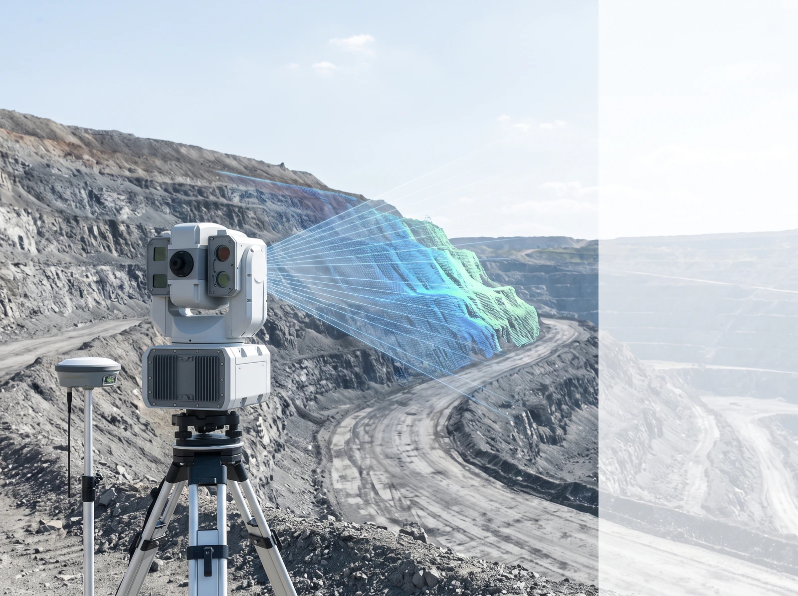
Ground-based interferometric radar can observe spatial movement patterns without installing a sensor on every point.

Selection note: Verify line of sight, range, update interval, stable reference and environmental or atmospheric corrections.

02Continuous displacement at selected structures or ground points

GNSS point monitoring

GNSS provides traceable point movement when monument, sky view, communications and reference quality are controlled.

Selection note: Use enough points to represent the movement model and define how loss or drift of a station is handled.

03Geometry capture, periodic comparison and independent confirmation

Laser or survey measurement

Laser scanning and conventional survey methods can document surface geometry or confirm selected movement.

Selection note: Control registration, reference stability, scan interval, target access and comparison methodology.

04Threshold calculation, mapping, notification and event reconstruction

Integrated alarm platform

The operating layer combines measurements, instrument health, configured alarm logic and acknowledgements.

Selection note: Keep raw evidence, calculation version, threshold changes, operator actions and degraded states auditable.

01

Movement model

Define expected displacement rate, direction, affected area and required warning lead time.

02

Measurement geometry

Validate line of sight, range, scan coverage, stable reference points and mounting conditions.

03

Operational response

Tie thresholds to named actions, responsible roles and independent verification.

Quick comparison

Deformation Monitoring product comparison
ModelPrimary roleSelected specificationsDetails
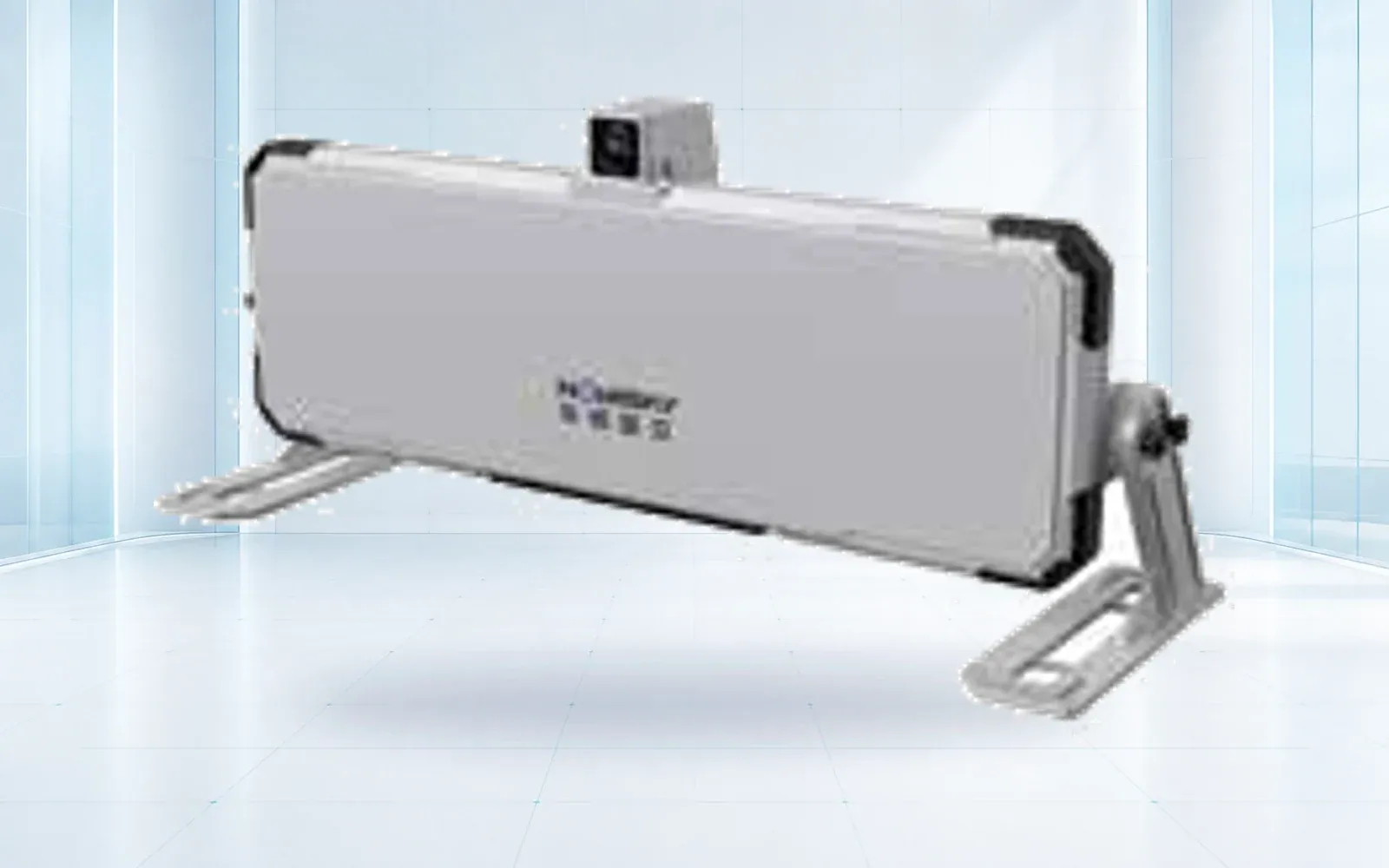
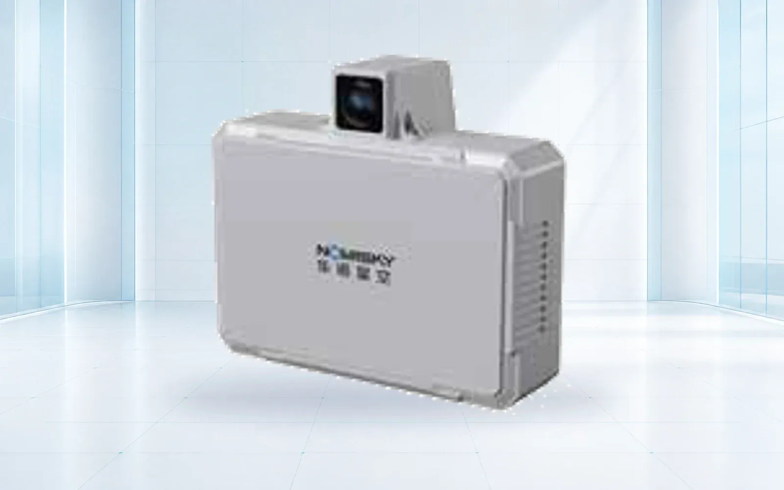
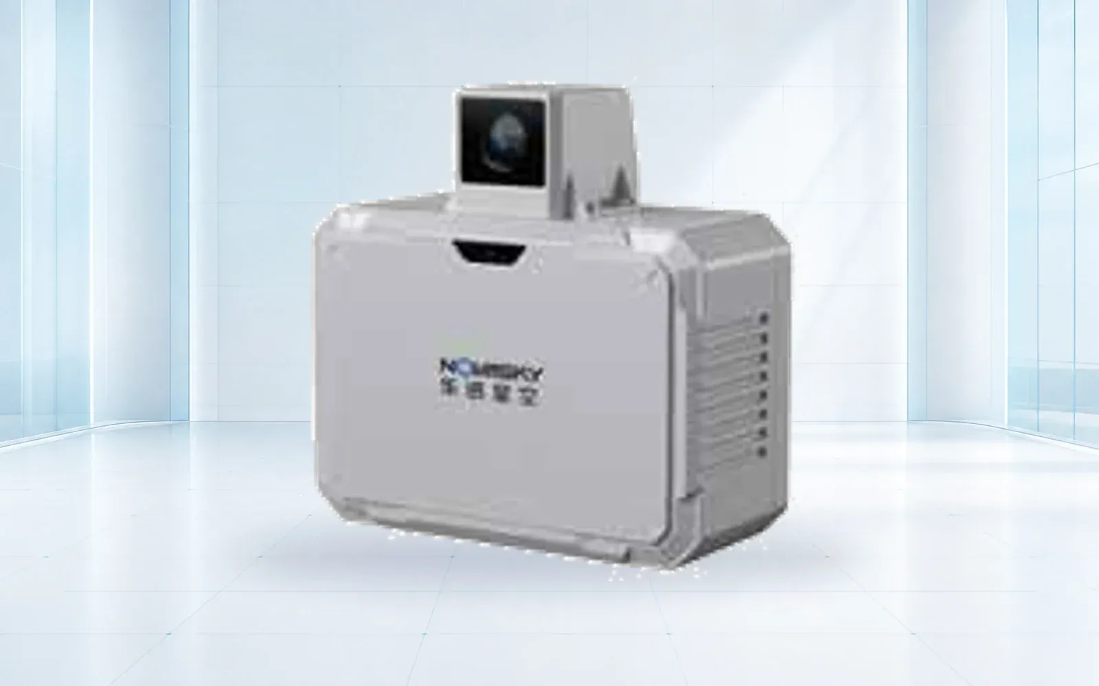
HAWK-R5Persistent deformation monitoringRadar type: Arc synthetic-aperture deformation radar · Signal: FMCWOpen →
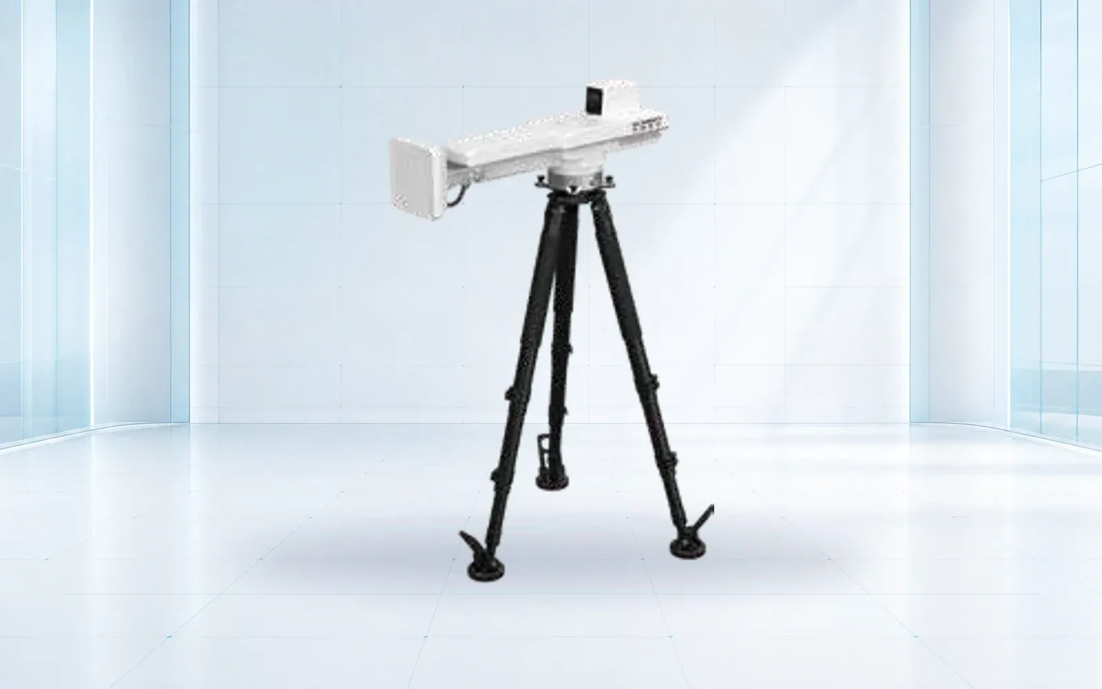
HAWK-R2SRapid field deploymentRadar type: Arc synthetic-aperture deformation radar · Signal: FMCWOpen →
HAWK-R6Fast-update deformation radarRadar type: MIMO deformation radar · Signal: FMCWOpen →
HAWK-R1SFixed-site monitoringRadar type: MIMO deformation radar · Signal: FMCWOpen →
HAWK-R1Remote structural displacementMeasurement: Remote deformation trend · Operation: Continuous, non-contactOpen →
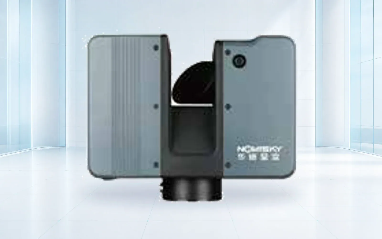
HAWK-RL1500Spatial surveySensor class: Terrestrial 3D laser scanner · Primary output: Georeferenced point cloudOpen →
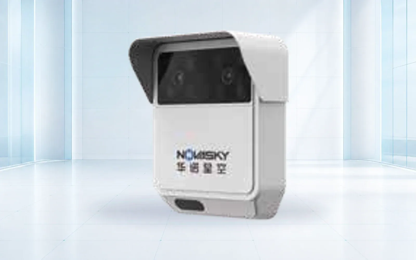
HAWK-R0DHazard event detectionSensor fusion: Radar and video · Monitoring mode: Continuous event detectionOpen →
HAWK-G902Point displacement monitoringSensor class: GNSS monitoring receiver · Deployment: Fixed monitoring pointOpen →

Buyer workflow

From requirement to accepted configuration

Use the same decision sequence for every shortlisted product so that published specifications, project assumptions and delivered evidence remain comparable.

  1. STEP 01

    Build the movement model

    Describe expected direction, rate, extent, precursors and assets or people exposed.

    Output: Hazard and warning-time statement

  2. STEP 02

    Design measurement geometry

    Map coverage, references, line of sight, power, communications and independent methods.

    Output: Instrument and reference layout

  3. STEP 03

    Write the alarm register

    Connect magnitude, velocity, persistence and confidence to verification and action.

    Output: Approved alarm and responsibility matrix

  4. STEP 04

    Commission the human system

    Inject alarms and outages under realistic staffing and verify the complete response.

    Output: Scenario and recovery evidence

Acceptance evidence

What the project should verify before handover

Acceptance areaRequirementEvidence
BaselineNormal environmental and operational variation is characterized.Reviewed baseline dataset and exclusions
MeasurementKnown or simulated movement is detected at the required location and interval.Controlled target or replay result
Alarm workflowNotification, acknowledgement, verification and action meet the plan.Timed alarm exercise
Degraded monitoringPower, reference or communication loss produces the agreed reduced-confidence procedure.Outage and restoration test

Before requesting a quotation

Questions a serious buyer should resolve

  1. 01Which movement pattern and warning time must the system support?
  2. 02What portions of the slope or structure are not visible from the proposed geometry?
  3. 03How are atmospheric effects, reference instability and instrument movement recognized?
  4. 04Who owns threshold definition, daily review, verification and alarm closure?
  5. 05Which independent method will be used when measurements conflict or monitoring is degraded?

Selection questions

Does a deformation sensor replace geotechnical judgment?
No. Instruments provide evidence and alerts; qualified personnel must define thresholds, interpret movement and decide operational actions.
How should alarm thresholds be set?
Thresholds should combine baseline behavior, rate of change, site hazards and response time. Multi-level alerts and independent confirmation are usually preferable to a single fixed value.
Can monitoring continue in poor weather?
Capability depends on instrument and installation. Radar can reduce dependence on light conditions, but rain, snow, vibration, power and communications still require site-specific assessment.
ENGINEERING & CONSULTATION

Configure a Deformation Monitoring system

Share the site, mission, payload, performance target and destination country. Our team will return a traceable configuration rather than a generic product list.

Start a technical inquiry