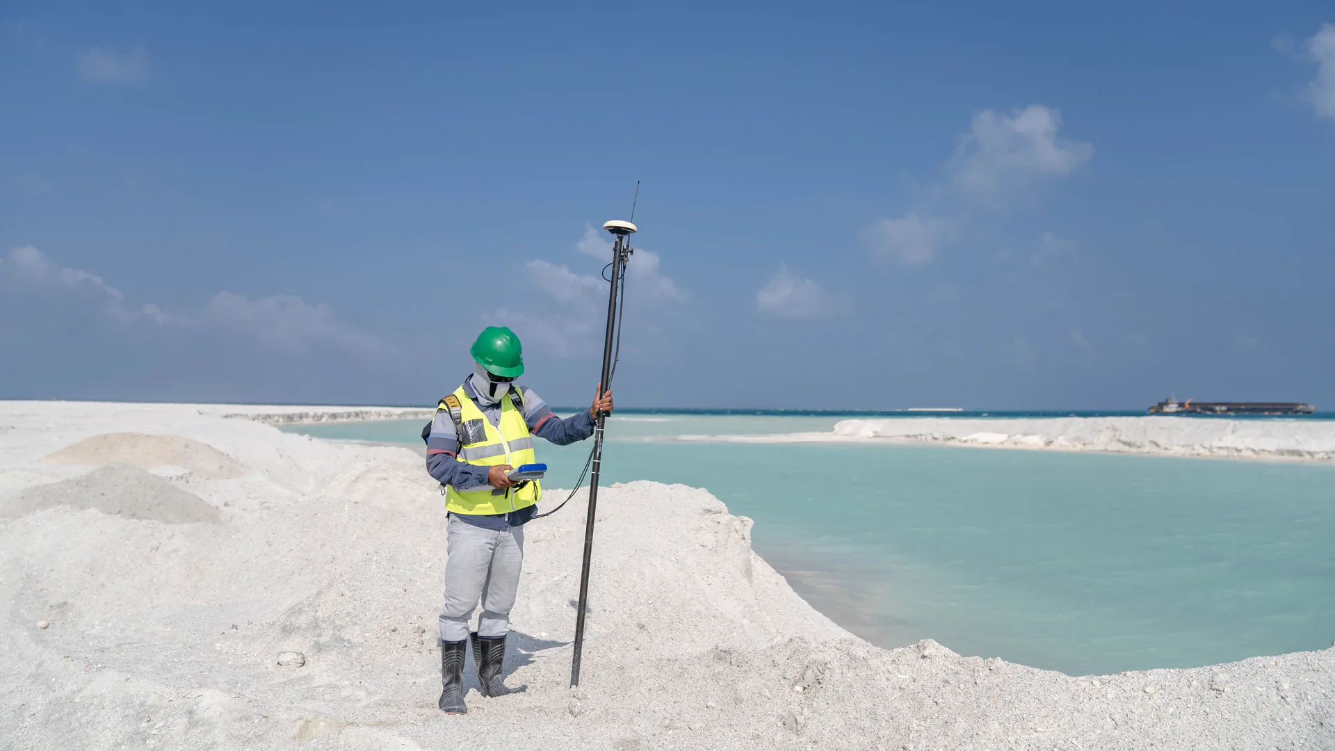
A GNSS monitoring system does not measure deformation in isolation; it estimates antenna coordinates inside a reference frame, under changing satellite geometry, atmosphere, multipath, monument behavior, processing, and communications. The engineering task is to turn that estimate—and its health and uncertainty—into a defensible movement decision.
Table of Contents
- Define the Movement Question and Coordinate Frame
- Design Reference and Monitoring Station Geometry
- Control Monument, Antenna, Power, and Communications
- Process Observations With Explicit Quality States
- Separate Movement From Uncertainty and Reference Change
- Build Alarm Logic Around Persistence and Corroboration
- Verify the System With Survey and Failure Tests
- FAQs
Define the Movement Question and Coordinate Frame
State what is expected to move, in which directions, over what time scale, and what decision the measurement supports. A bridge deck expansion pattern, slow slope displacement, dam crest settlement, retaining-wall movement, and mine subsidence need different station geometry, epochs, environmental interpretation, and alarm logic. “Millimeter monitoring” is not a complete requirement.
Choose a coordinate frame that makes the movement interpretable. Global coordinates are useful for traceability, but a local along-axis, cross-axis, and vertical frame may be clearer for an asset. Preserve the transformation and reference epoch. If the frame, antenna metadata, or processing model changes, flag a discontinuity rather than presenting the new series as seamless.
The NOAA National Geodetic Survey’s CORS coordinate policy describes coordinate changes associated with subsidence, hydrology, antenna or firmware changes, and other discontinuities. A project reference station faces the same conceptual problem: its coordinate is not beyond question simply because it is called a reference.
| Output | Must include | Can support | Cannot establish alone |
|---|---|---|---|
| Position epoch | Frame, time, solution status, uncertainty, station metadata | Location estimate at that epoch | Structural condition or cause |
| Displacement series | Reference epoch, filters, gaps, discontinuities | Trend, rate, correlation | Safety threshold without engineering basis |
| Velocity estimate | Time window, uncertainty, persistence | Escalation or trend review | Future failure time by default |
| Alarm state | Data health, logic, evidence window, authority | Defined protective or review action | Validity when reference or communications are unhealthy |
Define an error budget before selecting alarm thresholds. Include monument motion, antenna setup, multipath, satellite geometry, atmosphere, receiver and processing behavior, reference distance, transformation, temperature effects, data gaps, and any smoothing latency.
Design Reference and Monitoring Station Geometry
Place monitoring points where movement is mechanically meaningful and where the antenna can collect suitable observations. A point installed on a convenient railing may move, vibrate, or be disturbed independently of the structural element. Define the monument-to-asset load path and protect it from maintenance activity, impact, tampering, and water ingress.
Reference stations should be outside the expected deformation zone, but “farther away” is not always better. Baseline length, atmosphere, terrain, communications, access, and common-mode behavior all matter. Where consequences justify it, use multiple references or an external check so the system can distinguish target movement from reference movement.
Assess sky visibility and multipath at every site. Buildings, steel, rock faces, water, vehicles, cranes, vegetation, and changing construction can reflect or block signals. A clear installation photograph is insufficient; review observation quality across representative satellite geometry and seasons.
The NGS real-time GNSS user guidelines explain practical sources of real-time positioning error and the need for independent checks. They are geodetic guidance, not a project-specific alarm standard, but they provide a strong basis for requiring quality indicators and verification instead of trusting the fixed/float label alone.
Control Monument, Antenna, Power, and Communications
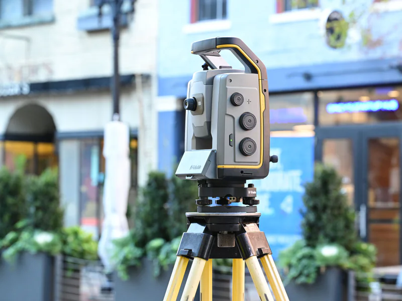
Document monument design, material, embedment, attachment, antenna mount, forced centering where used, antenna type and serial, radome, antenna height convention, cable, surge protection, enclosure, grounding, power, backup time, and communication path. Photograph the installation and record changes under configuration control.
Temperature can affect structures, mounts, cables, enclosures, and the asset itself. Record environmental variables needed to distinguish expected cyclic behavior from unexplained movement. Do not automatically remove temperature-correlated motion; model or classify it according to the engineering question and retain the unfiltered series.
Power and communications need supervised states. “No new displacement” and “no current data” must be visibly different. Monitor station heartbeat, receiver status, storage, correction age where applicable, packet delay, clock state, and backup-power condition. Buffer original observations locally when a network outage would otherwise create an irrecoverable gap.
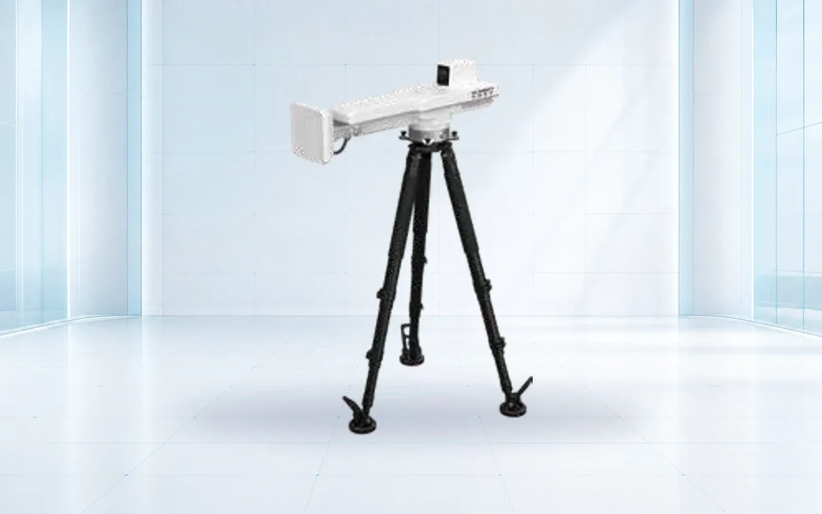
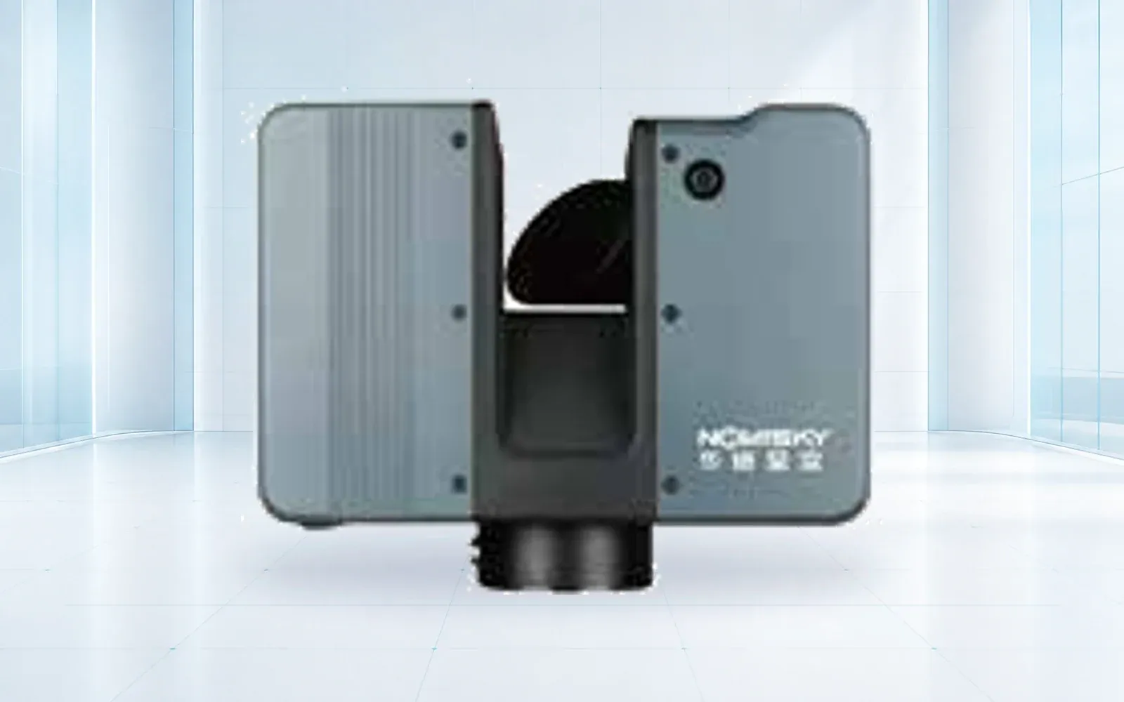
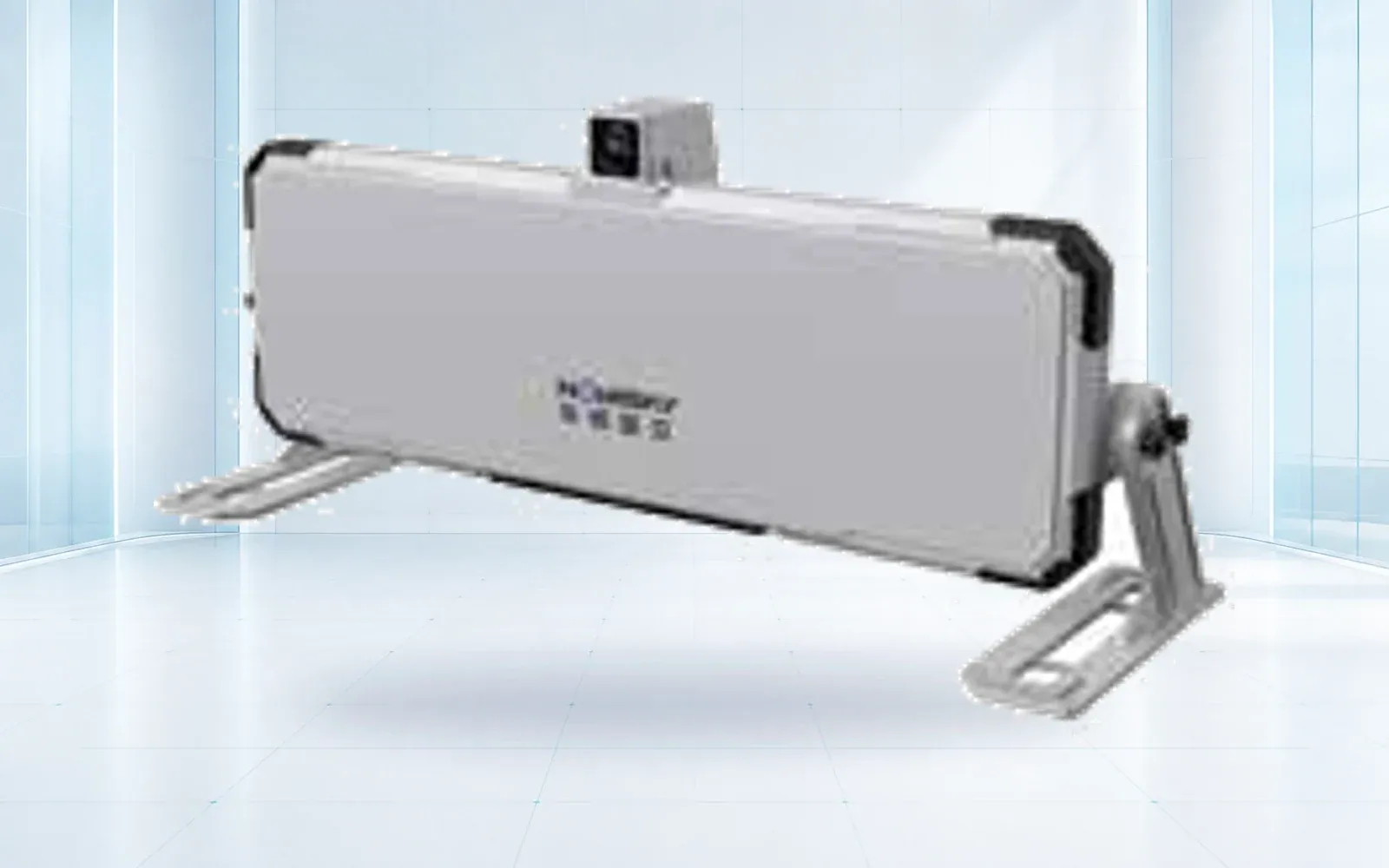
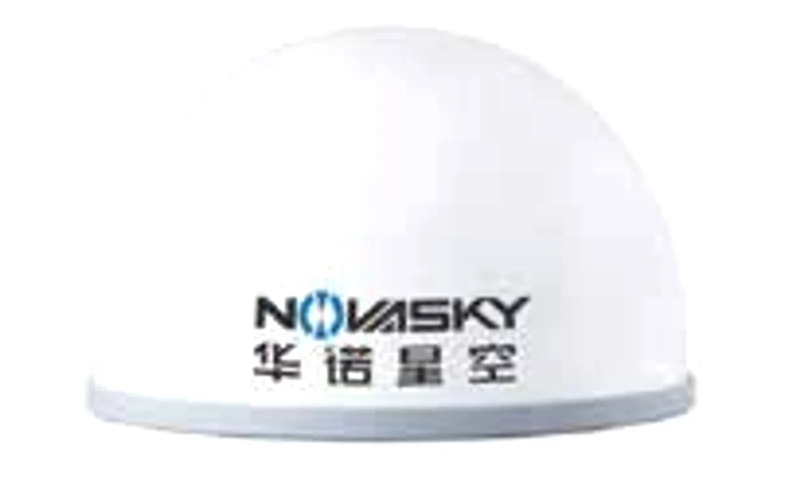
The HAWK-G902 GNSS receiver is a reference monitoring component. The HAWK-RL1500 3D laser scanner is a separate spatial-survey reference that may support periodic geometry checks where its verified accuracy and registration method fit. Verify the offered antenna, receiver, processing, enclosure, power, communications, software, and data export as one GNSS configuration; do not present a separate scanner as part of the continuous receiver chain.
Process Observations With Explicit Quality States
Preserve original observations at the rate and duration required for reprocessing. Store station metadata, antenna calibrations, ephemeris and correction sources, processing version, coordinates, covariance or uncertainty outputs, quality flags, excluded data, and reason codes. A dashboard-only history is not an auditable measurement record.
Define acceptable, degraded, invalid, and unavailable states. The state logic may consider observation count, satellite geometry, ambiguity status, residuals, correction age, cycle slips, multipath indicators, reference consistency, latency, and solution covariance. Thresholds should come from the installed system’s validation, not a generic screenshot.
Filtering trades noise against delay and signal distortion. A moving average that produces a smooth line may delay an abrupt change; aggressive outlier rejection may remove real movement. Document filter type, window, causal or retrospective use, and treatment of gaps. Present raw or minimally processed evidence alongside alarm-oriented products when appropriate.
The NGS draft real-time GNSS network guidelines provide useful network-quality concepts. For monitoring, extend them with asset-specific reference checks, persistent station metadata, and an engineering review trail.
Separate Movement From Uncertainty and Reference Change
Report displacement with its uncertainty and quality state. A 4 mm change with 8 mm uncertainty does not support the same conclusion as a 4 mm change with a validated 1 mm uncertainty. Conversely, a low formal covariance may omit monument instability or unmodeled multipath; uncertainty must reflect the full accepted method.
Use independent evidence to test the reference. This may include redundant references, periodic survey ties, stable check points, regional stations, optical survey, tilt, crack, radar, or environmental observations. The choice depends on failure modes and consequence. Correlated movement across every target may be a real regional signal, an asset-wide response, or a moving reference—not a reason to subtract it automatically.
Track discontinuities as events. Antenna replacement, firmware change, monument repair, cable work, processing update, reference-coordinate revision, and earthquake or construction activity can shift a series. Maintain pre- and post-change solutions with the documented relationship rather than editing history to appear continuous.
For a broader asset-sensing architecture, see the bridge monitoring system design guide. That page owns the multi-sensor bridge strategy; this guide provides the GNSS-specific evidence and uncertainty layer that can feed it.
Build Alarm Logic Around Persistence and Corroboration
Separate sensor-health alarms from movement alarms. A station outage, reference disagreement, high uncertainty, and delayed data need operational responses but should not be displayed as confirmed deformation. Likewise, do not suppress an urgent health failure merely because the last valid displacement was normal.
Use an alarm state machine rather than one threshold. A useful structure includes normal, watch, warning, alarm, data-degraded, and unavailable states, each with entry, persistence, exit, acknowledgment, and escalation rules. Magnitude, rate, acceleration, duration, spatial coherence, and corroboration can all contribute where the engineering basis supports them.
Assign authority and action to every state. A watch may prompt data review; a warning may trigger field inspection or increased sampling; an alarm may trigger an owner-approved protective action. The monitoring supplier should not invent asset-safety thresholds without the responsible engineer and owner.
Treat messages as safety-relevant outputs where consequences justify it. Record trigger data, logic version, send time, delivery, acknowledgment, operator decision, and closure. Exercise an unavailable primary communication path and define what local or alternate action remains possible.

Verify the System With Survey and Failure Tests
Commission monument and antenna installation, metadata, reference coordinates, local frame, time synchronization, power backup, communications, raw-data retention, processing, dashboard, exports, and alarm routing. Use an independent survey or calibrated displacement arrangement appropriate to the target accuracy.
Test zero movement over representative environmental cycles, known horizontal and vertical changes where practical, reference-coordinate change, target and reference outage, degraded observations, correction loss, packet delay, power transition, storage recovery, software restart, alarm persistence, acknowledgment, and return to service.
Score bias, repeatability, detection time, false-alarm behavior, uncertainty calibration, data completeness, reference-change detection, latency, and agreement with the independent method. Acceptance should specify the operating envelope, excluded conditions, maintenance interval, metadata controls, and retest triggers.
Review the deformation monitoring portfolio and technical resources, then contact OMNI UXV with the movement model, coordinate frame, expected rates, site geometry, consequence classes, error budget, alarm authority, and verification method.
FAQs
Can a GNSS monitoring system diagnose structural safety by itself?
No. GNSS can provide displacement evidence with stated uncertainty, but an engineer must interpret that evidence with the asset model, loading, environmental variables, other sensors, inspections, and the approved action plan.
Where should a GNSS reference station be installed for deformation monitoring?
Install it on a monument expected to be stable relative to the movement question, with suitable sky visibility, low multipath, secure power and communications, and an independent way to detect reference motion. Convenience alone is not a stability criterion.
Does real-time GNSS automatically support real-time alarms?
No. An alarm also requires observation-quality checks, reference health, uncertainty, persistence, rate or magnitude logic, corroboration where appropriate, communications supervision, authority, and a defined protective action.
How should a GNSS deformation monitoring system be accepted?
Verify monument and antenna installation, coordinate frame, known-displacement response, precision under representative conditions, reference-change detection, outage and recovery behavior, latency, data lineage, alarm logic, and independent survey agreement.