Terrestrial laser scanning and ground-based monitoring radar can both observe a slope or structure without installing sensors on every surface, but they answer different questions. Laser scanning captures three-dimensional geometry at defined epochs; interferometric radar emphasizes displacement along its line of sight over repeated cycles in coherent areas.
Table of Contents
Compare the Measurand Before the Instrument
A laser scanner samples ranges and angles to build a point cloud representing visible surface geometry. Comparing registered epochs can reveal shape or volume change. A ground-based interferometric radar measures phase change and derives displacement along the radar’s line of sight for coherent surface areas.
Write the required measurand: surface model, volume, bench or wall geometry, rockfall inventory, periodic change, frequent displacement trend, rapid movement input, or independent corroboration. Avoid asking either instrument to produce an undefined “monitoring result.”
Put Time and Space on the Same Decision Table
| Design factor | Terrestrial laser scanning | Monitoring radar | Reconciliation question |
|---|---|---|---|
| Native emphasis | Dense 3D surface geometry | Repeated line-of-sight displacement | Which observation supports the decision? |
| Time model | Discrete or automated scan epochs | Repeated configured cycles | Could important change occur between epochs? |
| Spatial support | Point cloud and derived surface | Radar-resolved coherent area | Are the compared areas physically equivalent? |
| Reference | Survey control and registration objects/surfaces | Stable radar reference and instrument position | Can reference movement be detected? |
| Surface change | Vegetation, excavation and material removal alter geometry | Coherence and return can change | Is apparent motion actually a changed surface? |
| Operational use | Mapping, condition, volume and change context | Trend, surveillance or alarm input when validated | Who reviews and what action follows? |
More points do not automatically mean more accurate change, and a rapid radar cycle does not automatically produce a complete vector. State the uncertainty and quality test for the actual output.
Protect the Reference Frame
Laser change detection depends on survey control, scanner position, target network, or surface registration. If the surfaces chosen for alignment move or are excavated, the difference model can absorb real change or create artificial change. Retain registration residuals and control checks by epoch.
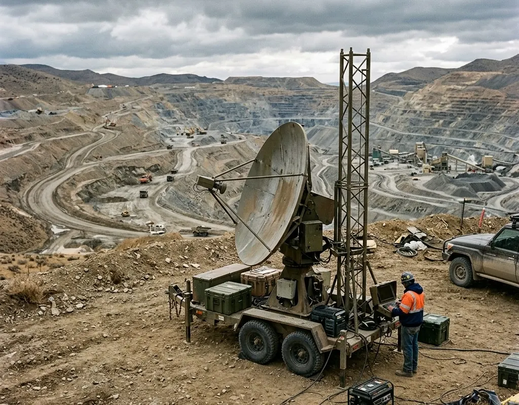
Radar requires a stable instrument and reference strategy. Atmospheric variation, surface moisture, vegetation, loose material, blasting, equipment, and reference-area change can shape the result. Display reference and coherence quality beside displacement.
USGS notes that monitoring inaccuracies can arise from instrument malfunctions and physical changes at the measurement site. Treat reference failure as an operational state, not a hidden processing detail.
Separate Geometry Change From Displacement Trend
Excavation, dumping, scaling, vegetation clearing, erosion, and rockfall can change the surface represented by a point cloud. Radar may lose coherence or begin observing a different reflector. Preserve operational logs so reviewers can distinguish planned work from hazardous movement.
Create a reconciliation record for every compared zone: source files, coordinate system, epoch or time window, reference, surface filter, observed component, difference method, uncertainty, environmental condition, quality mask, and interpretation owner.
FHWA instrumentation guidance shows why surface measurements do not replace subsurface and groundwater observations such as inclinometers and piezometers. Keep both remote methods inside the larger failure model described in the slope-instrument guide.
Design a Combined Workflow Without a Mystery Score
Use laser scanning to establish geometry, map access and occlusion, quantify selected surface changes, or provide scheduled independent context. Use radar for validated frequent line-of-sight observations over critical areas. Add GNSS, prisms, geology, water data, and field inspection where they answer other questions.
Do not average unlike data into one unexplained risk number. Preserve native quality and show why evidence agrees or conflicts. A radar change with no laser difference may reflect time-scale or spatial-support differences; a laser change between epochs may occur when radar data were unavailable or incoherent.
Accept Each System and the Handoff
For laser scanning, test control, registration, coverage, range, target resolution, repeat setup, processing, change detection, export, and recovery. For radar, test geometry, reference, coherence, environmental artifacts, revisit, independent movement, alarms, faults, and recovery. Then test the shared coordinates, zones, timestamps, event record, and review workflow.
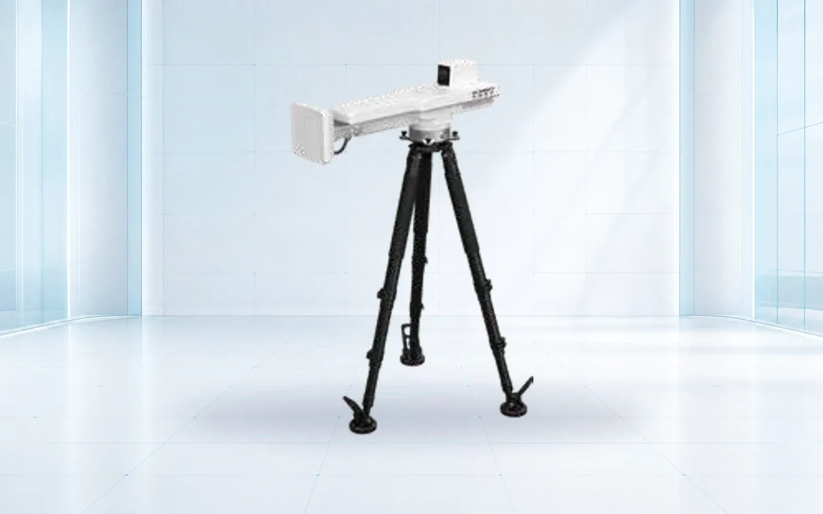
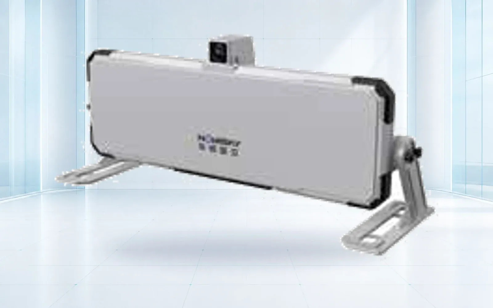
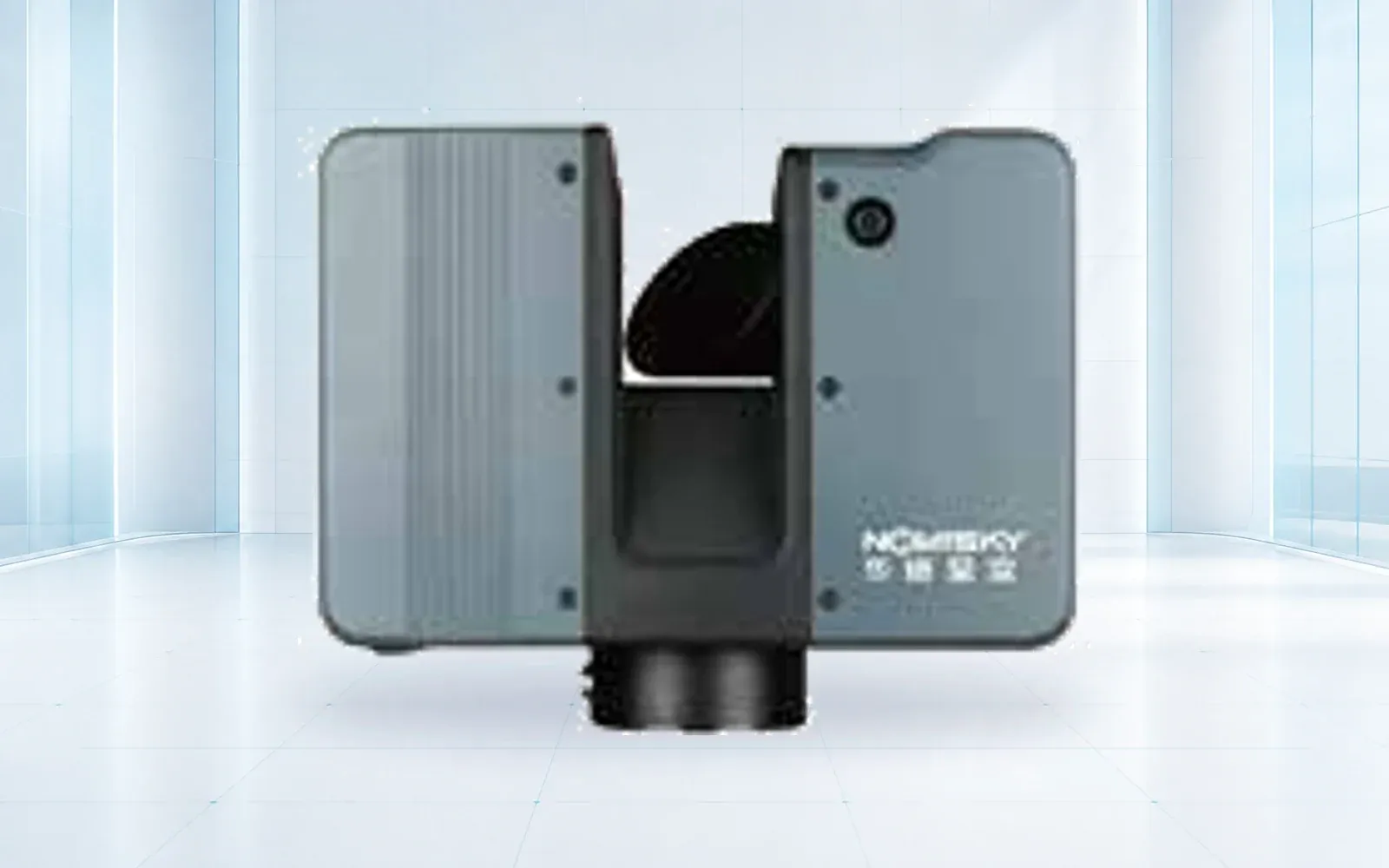
The HAWK-RL1500 laser scanner and HAWK-R6 radar are candidate measurement components to evaluate. Use the deformation category, mining-safety solution, and resource center to document the combined method and its limits.
FAQs
Can a laser scanner provide continuous slope alarms?
Some systems can automate repeated scans, but alarm suitability depends on scan interval, registration, processing latency, change detection, weather, quality control, and the validated operating workflow.
Does monitoring radar create a complete three-dimensional model?
Not by default. Its main deformation output is line-of-sight displacement over radar-resolved areas; a 3D surface or full movement vector requires additional geometry or measurements.
When should laser scanning and radar be used together?
Use them together when periodic 3D geometry or volume context and higher-frequency line-of-sight movement answer different parts of the same failure model, with common references and time control.