A slope monitoring system should not begin with a favorite sensor. Start with the failure mechanism, likely movement direction, water and subsurface questions, exposed people or assets, required warning time, access, and the decisions that observations must support; then assign each instrument a measurable role and a visible failure state.
Table of Contents
Build the Failure Model Before the Instrument List
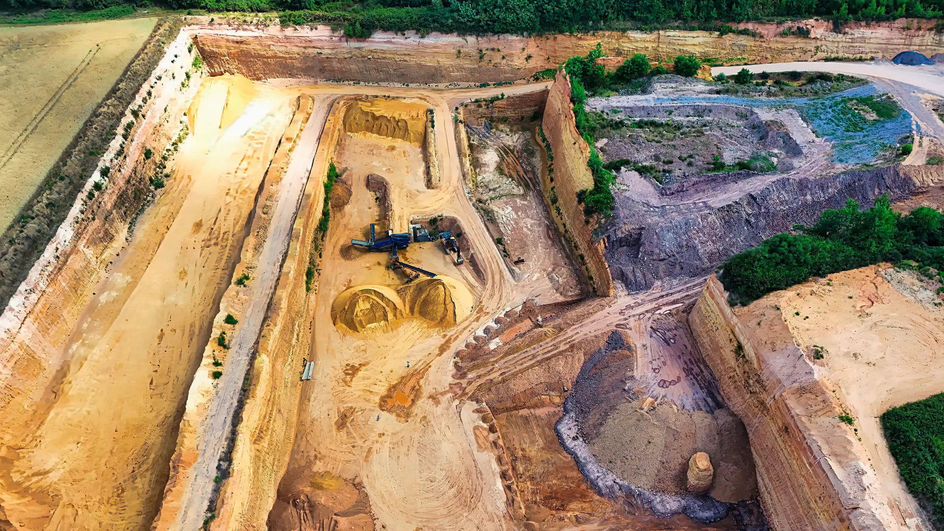
Identify plausible failure surfaces, movement direction, depth, extent, expected rate, triggers, water conditions, progressive indicators, exposed people and equipment, and the time required to verify and act. Map active work, blasting, excavation, drainage, seasonal change, access, power, communications, and safe instrument locations.
USGS cautions that monitoring data can be preliminary and affected by instrument malfunction or physical changes at the measurement site. Design quality flags, independent checks, and missing-data actions before an instrument becomes an alarm input.
Assign Each Measurement a Distinct Question
Do not combine instruments merely for redundancy. Choose complementary observations tied to the failure model.
| Method | Primary observation | Spatial/temporal role | Important boundary |
|---|---|---|---|
| Ground-based interferometric radar | Surface displacement along radar line of sight | Broad coherent area, frequent cycles | Direction sensitivity, atmosphere, occlusion and coherence |
| GNSS | Three-dimensional point position | Selected monuments, continuous or periodic | Sparse points, monument and reference stability |
| Prism/total station | Survey line-of-sight position at points | Scheduled or automated point network | Visibility, references and atmospheric effects |
| Laser scanning | Dense surface geometry by epoch | Wide geometry and change snapshots | Registration, surface change and revisit interval |
| Inclinometer | Subsurface lateral deformation profile | Installed borehole, manual or automated | Point location, installation and casing behavior |
| Piezometer | Pore-water pressure | Installed point and sampling interval | Represents water, not displacement |
| Field observation | Cracks, drainage, rockfall, material and operations | Direct context at accessible areas | Access, subjectivity and intermittent coverage |
FHWA describes inclinometers as a way to observe subsurface lateral deformation and piezometers as instruments for pore-water pressure. Those measurements answer different questions from a surface radar trend.
Design Coverage, References, and Failure Visibility
For every instrument, record the hazard zone observed, blind area, physical reference, coordinate frame, time source, sampling interval, data path, power, environmental limit, health signal, maintenance access, and the action taken when data are missing or suspect.
References can fail. A radar reference area may move or lose coherence; a GNSS reference can be disturbed; a prism may be occluded; a scan registration may use surfaces altered by mining; a borehole casing can be damaged. Make reference quality visible to the operator instead of applying silent correction.
Reconcile Time, Direction, and Uncertainty Before Correlation
Convert data only after documenting axes, sign convention, reference, units, filter, timestamp, averaging window, and uncertainty. Radar line-of-sight displacement should not be compared directly with a full GNSS vector or a laser surface difference without projecting or reconciling the observed components.
Sampling intervals also matter. A daily survey, satellite revisit, continuous GNSS feed, and rapid radar cycle describe different windows. A short event can appear in one stream and be averaged away or absent in another. Preserve native values and quality fields before producing a combined view.
The InSAR versus ground-based radar guide covers regional and local radar scales, while the laser-versus-monitoring-radar guide focuses on geometry epochs and continuous motion.
Connect Evidence to Named Actions
The geotechnical and operating teams should own an alarm register that maps observation, persistence, quality, corroboration, operating state, verification, authority, and action. Avoid one universal threshold copied from another site. Include missing-data, reference-failure, and conflicting-sensor states.
MSHA highwall guidance emphasizes examinations, hazard recognition, and restricting access until unsafe conditions are corrected; technology does not replace those ground-control practices. Use the slope alarm design guide to connect measurements to work controls.
Accept the Complete Monitoring System
Test installation geometry, references, baseline, data quality, known or independently observed change, environmental artifacts, power and communications loss, clock error, sensor movement, missing data, alarm routing, acknowledgment, evidence export, backup, restore, and operator handoff.
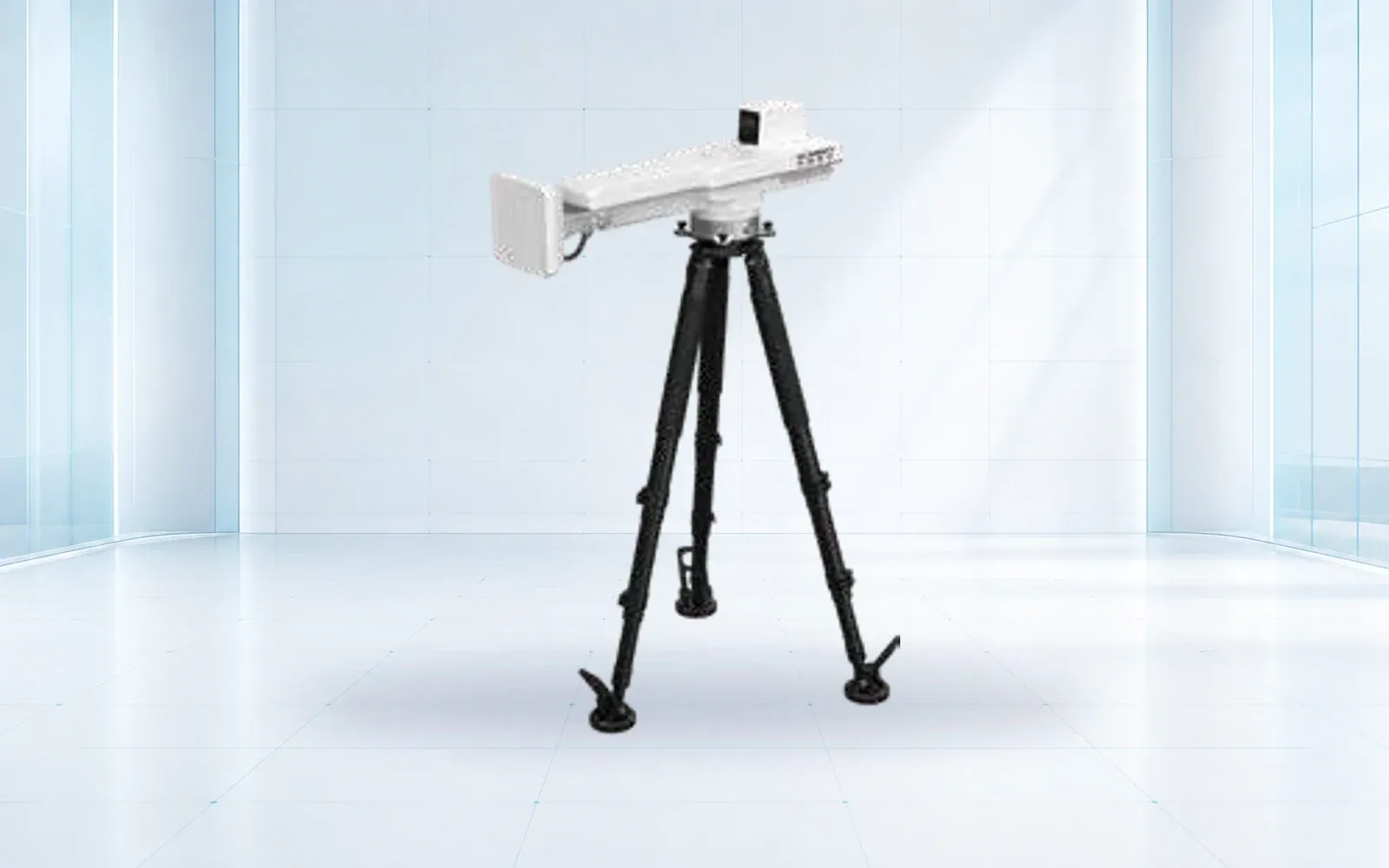
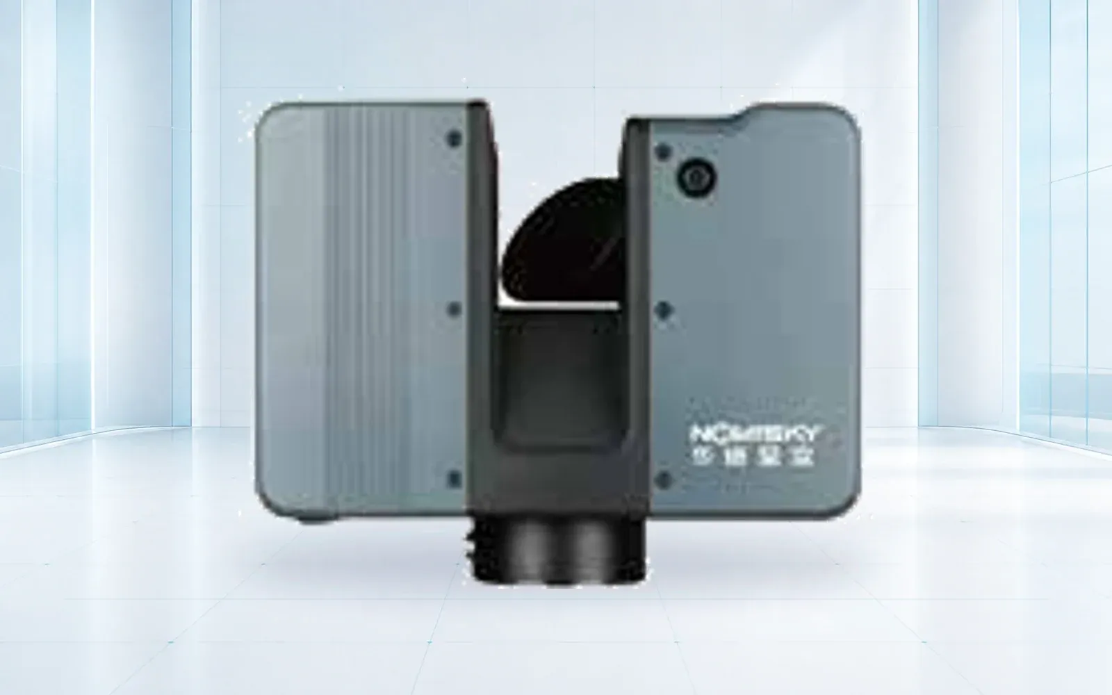
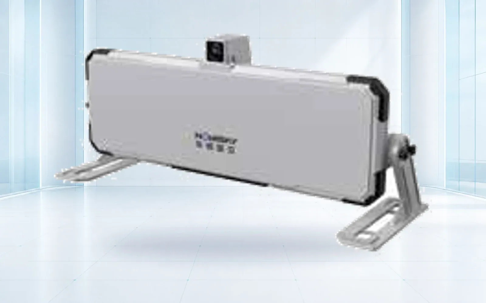
The HAWK-R6 radar, HAWK-G902 GNSS receiver, and HAWK-RL1500 laser scanner represent different measurement roles to verify. Use the deformation-monitoring category, mining solution, and resource center to organize the failure-mode matrix and acceptance record.
FAQs
Which instrument is best for slope monitoring?
There is no universal best instrument. Surface movement, subsurface shear, pore pressure, broad-area change, point displacement, geometry, and visual evidence require different methods and often independent corroboration.
Can slope monitoring radar replace inclinometers and piezometers?
No. Radar observes surface displacement along its line of sight over coherent areas; inclinometers can observe subsurface lateral movement and piezometers measure water pressure at installed points.
How should multiple slope instruments be integrated?
Align coordinates, time, reference stability, observed component, sampling interval, quality state, uncertainty, zone naming, and the decision each instrument supports before comparing or correlating data.
Does monitoring prove that a slope is stable?
No. Monitoring provides observations subject to coverage, uncertainty, failure, and interpretation. A qualified geotechnical process combines the data with geology, inspection, analysis, and operational controls.