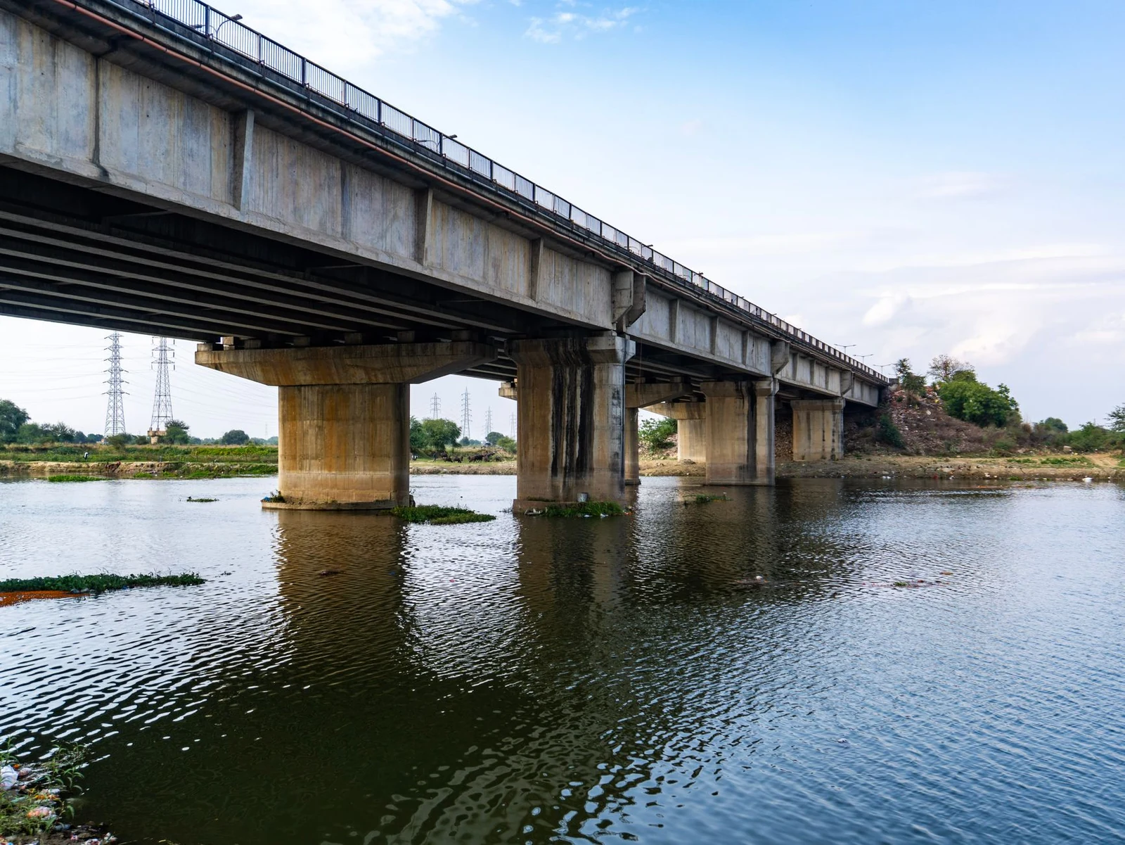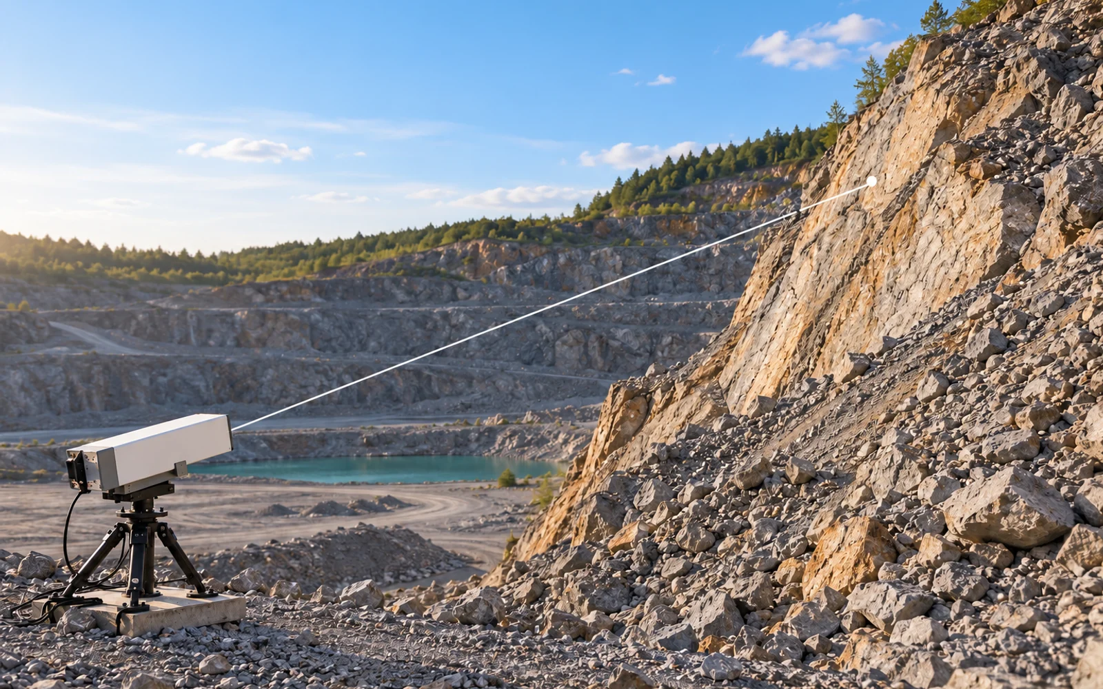
Interferometric radar measures the component of movement along its viewing direction. A slope can move substantially while producing a small line-of-sight signal if its motion is nearly perpendicular to that direction. Coverage planning therefore needs both visibility and sensitivity to the movement the engineer expects.
Table of Contents
What does line-of-sight displacement mean?
Line-of-sight displacement is the component of a displacement vector projected onto the radar’s viewing direction. It is not automatically the full downslope movement, vertical settlement or three-dimensional displacement.
The USGS InSAR methodology describes interferometric range change and shows that interpreting it as vertical motion requires an assumption about direction. The same projection concept is relevant to a ground-based interferometric radar, although its acquisition geometry and processing differ.
Before comparing plots, define whether positive means toward or away from the radar. Also identify the reference area, start time and any resets. Two displays can show opposite signs for the same movement because their conventions differ.
How much motion can geometry hide?
For motion magnitude d at angle θ to the sight line, the measured component is dLOS = d × cos θ. This simple model assumes the motion direction is known and ignores other measurement errors.
| Illustrative motion | Angle to sight line | LOS component |
|---|---|---|
| 10 mm | 0° | 10.00 mm |
| 10 mm | 30° | 8.66 mm |
| 10 mm | 60° | 5.00 mm |
| 10 mm | 80° | 1.74 mm |
These values describe geometry, not an alarm threshold or the performance of a particular radar. Close to 90 degrees, dividing the measurement by a small cosine greatly magnifies uncertainty. If the true direction is uncertain, the corrected number can become less defensible than the original LOS observation.
A weak signal should trigger a geometry review, not an automatic conclusion that the area is motionless.
Build a sensitivity map, not just a visibility fan
For each area of concern, document the expected movement direction, radar position, clear sight line, coherent surface and potential masking. A target inside the instrument’s nominal range may still have poor sensitivity to the motion of interest.
Use the geotechnical model to identify plausible directions. Where the model is uncertain, record alternative scenarios. Assess whether another observation direction or a different instrument can reduce the ambiguity.
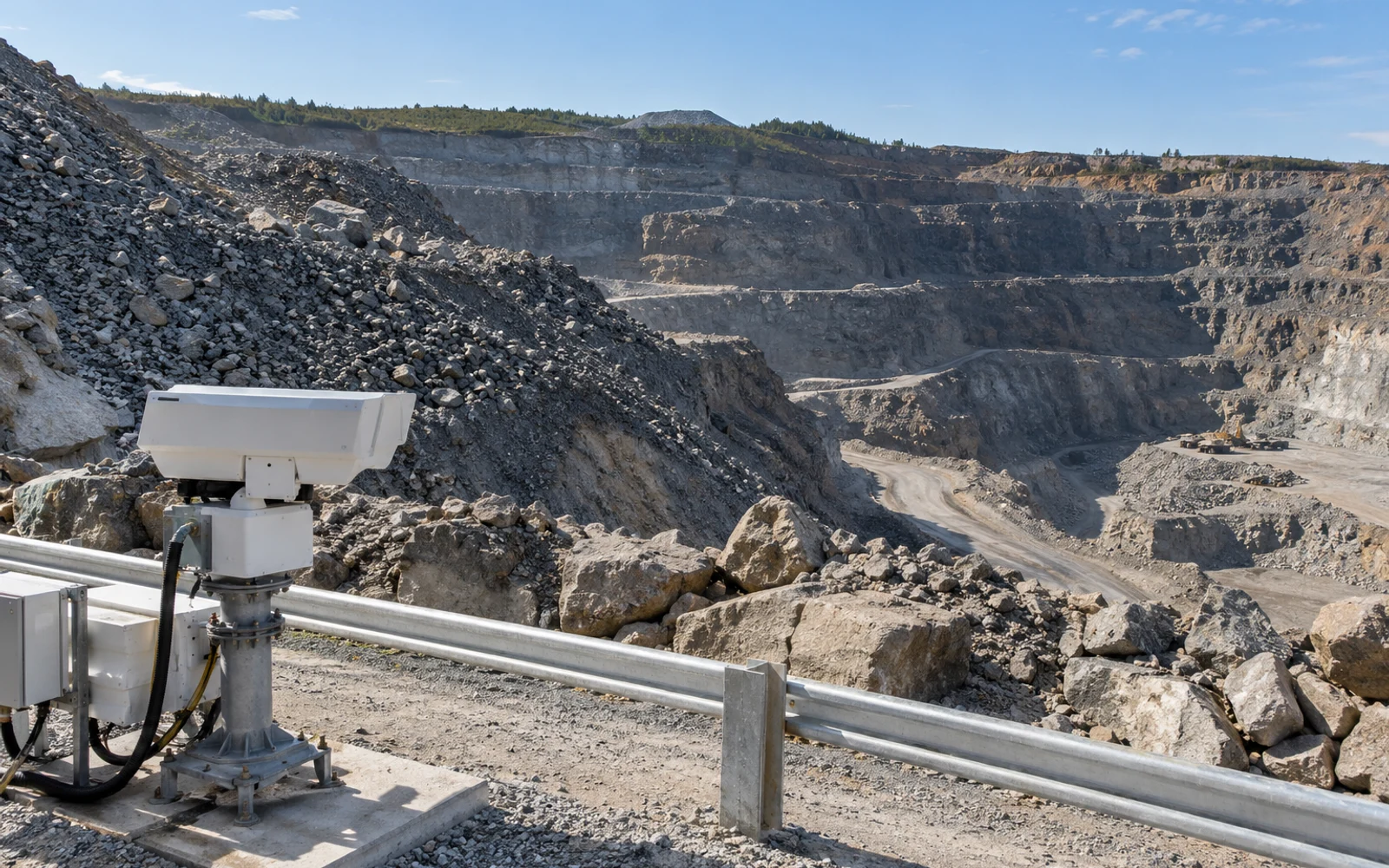
Visibility can also change as excavation advances, vehicles park or material is stockpiled. Track those changes against the accepted coverage map. The radar acceptance guide explains why usable coverage must be demonstrated in the installed setting.
Why can two monitoring systems disagree?
Radar cells, prisms and GNSS stations often observe different physical locations and spatial scales. A radar cell may include several scatterers; a prism represents its mounting point. Different references, filtering and averaging intervals can create additional differences.
Transform coordinates and align time intervals before comparing trends. Project an independently measured displacement vector onto the radar sight line when the geometry is known, rather than comparing its full magnitude directly with LOS.
Review reference stability and quality flags before declaring that one sensor is wrong. Keep differences visible when they cannot be resolved. The instrument selection article explains the distinct measurements available.
Put the interpretation limits in the monitoring plan
Deliver the coverage and sensitivity map, sign convention, reference definition, geometry assumptions and independent-check method with the monitoring configuration. Any conversion to another displacement component should retain its assumptions.
Keep the installed viewing geometry with the movement interpretation and response plan. A small line-of-sight change can reflect either small movement or a movement direction poorly observed from that radar position.
FAQs
Does zero line-of-sight displacement prove a slope is stable?
No. Motion may be nearly perpendicular to the viewing direction, below the usable measurement sensitivity or obscured by data-quality limitations.
Can radar displacement be divided by a cosine to get true motion?
Only when the motion direction is justified and the geometry is suitable. Near-perpendicular geometry amplifies uncertainty and can make that conversion unreliable.
Why compare radar with GNSS or prisms?
Independent measurements can observe other motion components or check reference behavior. Compare their coordinate frames, locations and time intervals before interpreting differences.