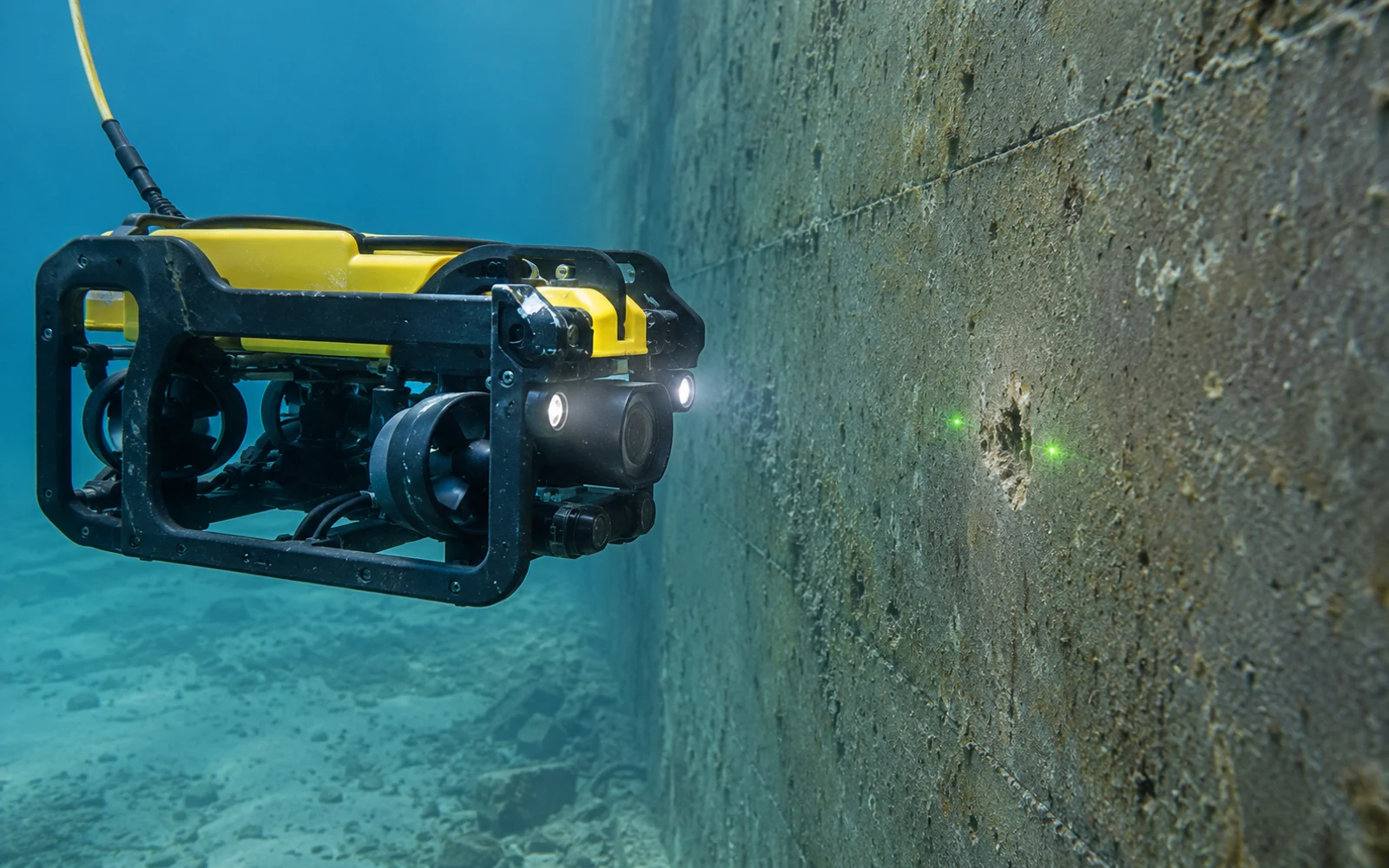
Two laser dots can give an ROV image a useful scale reference, but they do not make every object in the frame measurable. Surface angle, depth differences, lens distortion and mounting alignment determine whether a pixel comparison supports a defensible size estimate.
Table of Contents
What do two laser dots establish?
A calibrated pair of parallel lasers supplies a known beam separation. When the target geometry and camera view are suitable, the visible dots help establish a local image scale. They do not independently establish distance, orientation and three-dimensional shape for everything nearby.
The manufacturer overview from SubC Imaging distinguishes dot, line and grid tools and describes alignment and mounting considerations. Use the documentation for the actual installed camera and laser assembly; a spacing or accuracy quoted for another product is not transferable.
Keep this task separate from obtaining a clear view. The ROV camera guide for turbid water addresses lighting, visibility and standoff. Good visibility is necessary for picking measurement points, but it does not remove geometric uncertainty.
When does the pixel-ratio shortcut fail?
A simple pixel ratio assumes that the reference and measured feature share a suitable plane and imaging scale. It can fail when one dot falls on a protrusion, the feature lies behind the reference surface, the camera is oblique, or distortion differs significantly between the relevant image regions.
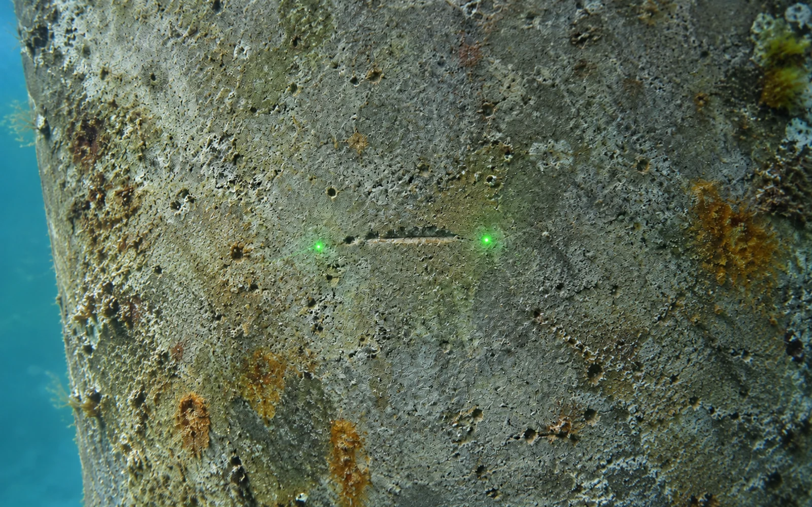
A cylinder is a useful warning case. Two dots on its curved surface do not automatically establish a flat scale for a feature elsewhere around the circumference. Likewise, a diagonal scratch and a horizontal dot separation may experience different foreshortening in an oblique view.
Treat the following table as a screening tool before reporting a number.
| Image condition | Why a simple scale may fail | Better next step |
|---|---|---|
| Dots and feature on one nearly frontal flat patch | Residual alignment and lens effects still exist | Verify against a known target in representative water |
| One dot on a raised edge | Reference and feature do not share depth | Reposition or use another measurement method |
| Strongly oblique view | Direction-dependent perspective affects dimensions | Use a validated geometric model or reacquire |
| Curved surface | Local scale changes across the object | Restrict the estimate or use calibrated 3D measurement |
| Broad, blurred or partly hidden dots | Pixel endpoint selection becomes uncertain | Improve acquisition; do not overstate precision |
An illustrative size calculation
Assume a verified laser separation of 100 mm, a dot separation of 400 pixels and a feature length of 120 pixels. Under a validated common-plane, suitable-view approximation:
Estimated length = 100 × 120 / 400 = 30 mm.
For an actual measurement, use the installed laser spacing, the selected pixel positions and the surface geometry in place of the example inputs.
As a sensitivity check only, changing the selected feature length from 120 to 124 pixels changes the estimate to 31 mm with the other inputs fixed. That does not establish a ±1 mm uncertainty: calibration, geometry, optical effects and repeatability are additional contributors.
Before production, compare measurements against a known reference using the same camera housing, settings and intended viewing range. Retain failed trials as well as accepted ones. A successful check in air does not alone characterize the full underwater imaging arrangement.
Record the frame that supports the number
Keep the original image or video and its exact frame/time reference. Save a separate annotated copy showing the dots and selected feature endpoints. Document the physical reference spacing, calibration date, mounting state, calculation method and reason the geometry was acceptable.
If software rescales or crops the image, confirm that both reference and feature measurements are made in the same coordinate representation. Avoid mixing a pixel distance from a preview window with another from an exported original.
Report what was estimated: visible surface-mark length, apparent opening or projected width. Do not turn a visible mark into an unsupported corrosion, crack-depth or structural diagnosis. Preserve the link to the asset identifier and inspection location so another analyst can find the same observation.
Escalate beyond visual scaling when needed
If the engineering decision needs tighter uncertainty, complex geometry or a quantity the image cannot reveal, use an appropriate calibrated measurement method and qualified interpretation. A missing or invalid scale is a reason to qualify the observation, not to invent a dimension.
For underwater inspection systems supporting port asset work, put the measurement acceptance method in the scope before mobilization. Define laser-use controls from the actual equipment instructions and site safety procedure; this illustration is not an operating procedure.
Each reported dimension should be traceable to its image frame, installed laser spacing and accepted surface geometry. Retain rejected measurements as coverage exceptions when another method is needed.
FAQs
Do two underwater laser dots provide a complete 3D measurement?
No. They can support a local scale reference under suitable geometry, but do not by themselves recover the three-dimensional shape or orientation of an arbitrary object.
Can the same pixel scale be used across the whole ROV image?
Not automatically. Perspective, lens distortion and depth differences can change the relationship between pixels and physical dimensions. Validate the geometry and restrict measurements to the supported region.
What should accompany an ROV image-based size estimate?
Retain the original frame, laser calibration and alignment record, geometry assumptions, marked endpoints, calculation, uncertainty or limitations, and the reason the estimate is suitable for its intended use.