An ROV manipulator must do more than lift a quoted mass. It needs to reach the work, orient the tool and apply force without making the vehicle lose its useful position. Select the arm and vehicle together, using the task's geometry and reaction loads.
Table of Contents
Start with the task at the tool tip
A simple gripper that holds an object and an articulated arm that aligns a probe perform different jobs. Write the task as a motion and force problem: reach a point, orient the tool, establish contact, perform the action and withdraw.
Reach Robotics’ Falcon integration account describes integrating a manipulator with an inspection-class ROV and notes balancing work during testing. That example illustrates why an arm is a vehicle integration project. It is not evidence that every inspection ROV can carry the same arm or perform the same intervention.
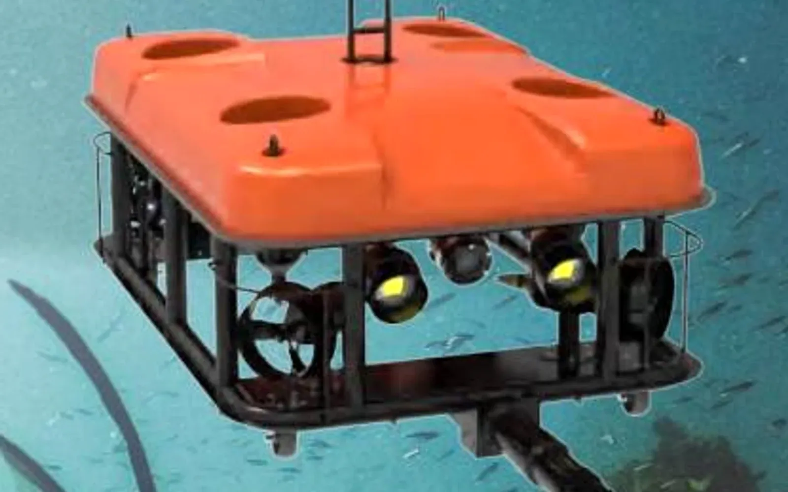
For an underwater ROV system, the shortlist should connect tool function, arm geometry, vehicle stability and the operator’s view.
What happens when the arm extends?
An applied force produces a moment about the vehicle according to its perpendicular lever arm: M = F × l. A hypothetical 40 N force acting 0.25 m from the relevant reaction point creates 10 N·m. At 0.50 m, the moment is 20 N·m.
The example is static and simplified. Current, tether loads, acceleration, contact direction and thruster authority also affect the vehicle. The useful lesson is that the same force can become harder to control as the arm extends.
A quoted lift capacity is therefore insufficient without the pose and load direction. Underwater apparent weight also differs from weight in air. Use the exact manufacturer’s load envelope for the selected arm, then evaluate the complete vehicle’s response.
Build a tool-interface matrix
| Interface | Design input | Consequence of a mismatch |
|---|---|---|
| Mechanical | Mount, reach and collision envelope | Tool cannot access the work or strikes the frame |
| Force and moment | Required contact force and pose | Vehicle moves instead of completing the task |
| Buoyancy and trim | Installed arm and tool state | Persistent attitude or control burden |
| Electrical | Supply, peak load and protection | Reset or power conflict during actuation |
| Data and control | Commands, feedback and safe state | Ambiguous action or loss of feedback |
| Observation | Camera angle and lighting | Operator cannot judge contact or clearance |
The ROV buoyancy and trim guide covers configuration balance. Manipulator selection adds changing geometry: the arm may move the center of mass and present different drag areas throughout a task.
Test the interface as a chain. Command the tool through its full range while recording supply current, communication errors and vehicle attitude. A tool that passes a bench test can still reset the vehicle when its actuator starts against a load. The test should include the emergency stop and the behavior after a lost command.
An end effector can also obstruct the camera precisely when contact matters. Include the wrist, tool and target in the view assessment rather than verifying only that the forward camera remains operational.
Compare manual work and repeatable intervention
The value of additional degrees of freedom depends on the task. A more dexterous arm can reach a difficult orientation, but adds controls, integration and operator workload. A simpler tool can be easier to operate when the work geometry is repeatable.
For port inspection and intervention, a useful demonstration includes the difficult approach and withdrawal, not just grasping an object in open water. Use a representative fixture and agreed load conditions. Measure whether the vehicle can maintain a useful view and position while the tool acts.
Define the behavior after loss of communications or power with the exact tool supplier. The desired state depends on whether releasing or retaining the object creates the greater risk in the intended task.
Select the least complex combination that completes the required motion and force task with an observable, recoverable operating sequence. The technical handover resources should include the arm, tool, mounting and control configuration as one baseline, so a later tool change is assessed against the accepted vehicle behavior.
FAQs
Is maximum lift the same as force at full reach?
No. Joint geometry and leverage change the loads through the arm. Use the manufacturer's configuration-specific load information and assess the vehicle's ability to react the task forces.
Can buoyancy foam compensate for an added arm?
It can help with net buoyancy, but its location also changes trim and stability. Evaluate the complete installed configuration rather than adding buoyancy solely by total mass.
Does a compatible connector establish tool compatibility?
No. Power limits, voltage, pin assignment, communications, command behavior, sealing and mechanical attachment must also match. A connector shell alone does not define the interface.
Should the arm be selected before the vehicle?
No. The arm, tool, mount and vehicle form one configuration. Selecting the arm first can leave insufficient thrust, buoyancy or viewing geometry; evaluate the combined system against the task.