Underwater buyers often mistakenly compare vehicles first. Instead, before asking how to choose an underwater ROV and sonar, you must first define the specific evidence your operation requires—whether that is a rapidly searched corridor or a highly detailed close inspection. The technical choice between side scan sonar vs imaging sonar depends entirely on whether you are scanning wide expanses of open seabed or navigating tight structures in zero visibility. Ultimately, proper multibeam sonar selection and deploying a capable underwater inspection ROV must be integrated to form a complete, repeatable evidence chain from search to final report.
Table of Contents
- Defining the Core Requirement
- Different tools answer different questions
- Water conditions decide what is practical
- Evidence and Operations
- Positioning makes evidence reusable
- Commission the system as a crew
- Procurement and Testing
- Score the mission before scoring equipment
- Include the surface system and mobilization
- Prove a representative evidence workflow
- FAQs
Defining the Core Requirement
Different tools answer different questions
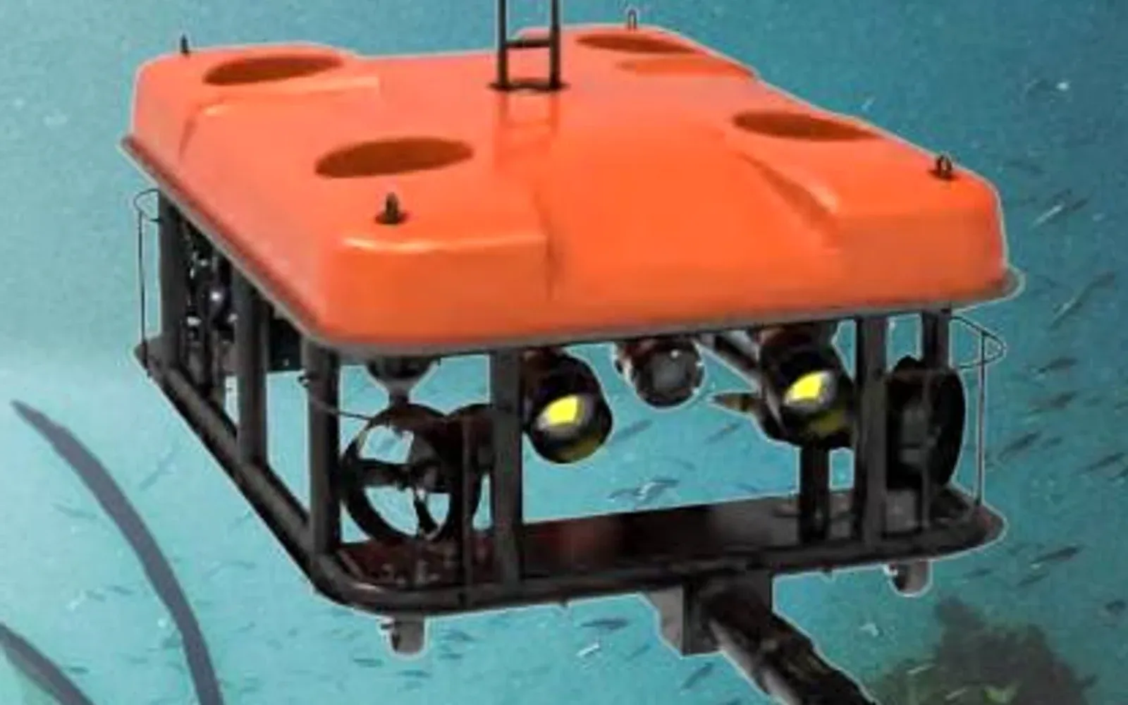
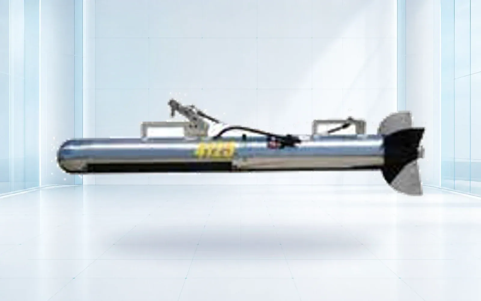
Side-scan sonar is well suited to searching a corridor and identifying seabed anomalies for follow-up. Multibeam systems measure depth across a swath and support bathymetric surfaces. Imaging sonar gives an operator near-real-time acoustic awareness around a structure when optical visibility is poor. An ROV carries eyes and tools to the point of interest.
| Required evidence | Likely starting tool | Typical follow-up |
|---|---|---|
| Search a seabed corridor | Side-scan sonar | Reacquire and classify anomalies |
| Build a depth surface | Multibeam echo sounder | Validate coverage and sound-velocity corrections |
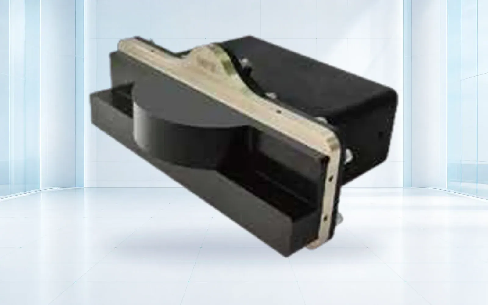
| Navigate near a structure in low visibility | Imaging sonar | Capture close acoustic and visual evidence |
| Inspect or manipulate a known target | ROV | Record position, video, tooling and task result |
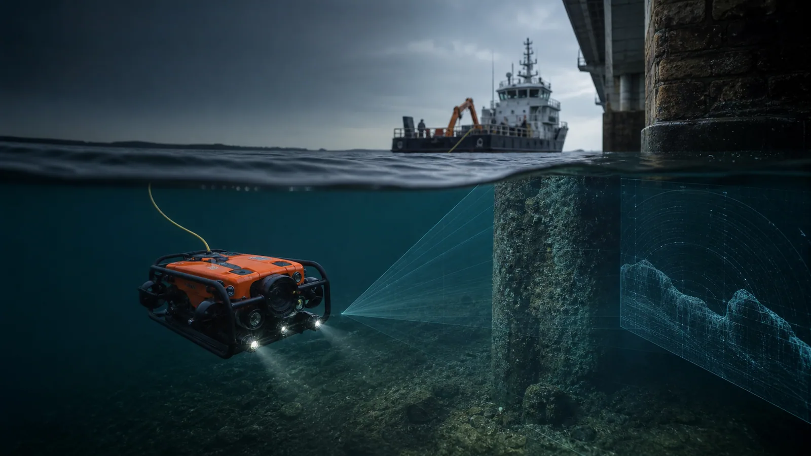
A common workflow uses more than one: search broadly, classify targets, then deploy an ROV for visual or acoustic confirmation. NOAA’s ROV technology overview explains the vehicle and tether relationship, while the underwater ROV and sonar guide and product catalog organize available reference configurations by evidence requirement.
For continuous linear assets, the underwater pipeline inspection guide extends this selection logic into route coverage, subsea position uncertainty, anomaly records and integrity-team follow-up.
Water conditions decide what is practical
Depth rating does not describe the whole operating envelope. Current affects vehicle authority and tether shape. Turbidity limits cameras. Fouling and suspended material change cleaning and acoustic conditions. Salinity, temperature and connector management affect reliability.
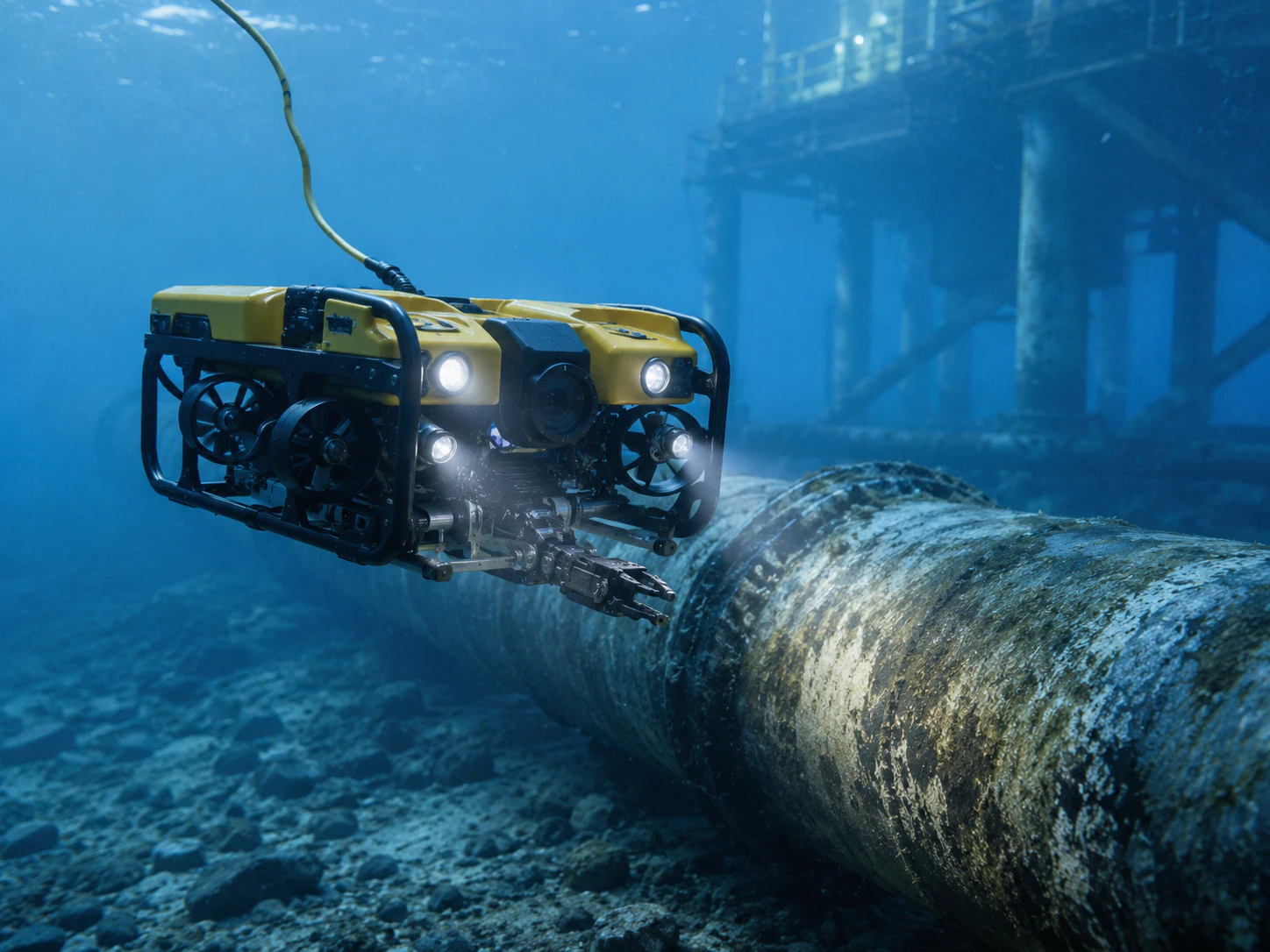
Record expected depth, current, launch height, stand-off distance and obstructions. Then evaluate propulsion, tether, sensor field of view and surface power together.
Evidence and Operations
Positioning makes evidence reusable
A clear image with no reliable location may be difficult to compare later. Define how the vehicle, towfish or acoustic target will be positioned, synchronized and logged. For repeat inspections, use stable naming, route references and calibration records.
The deliverable should say what was inspected, when, under which conditions, with which configuration and how each finding can be relocated. This is particularly important in a port and water security architecture, where search, incident evidence and repeat inspection may share the same data.
Commission the system as a crew
Launch and recovery, tether handling, piloting, sonar interpretation and deck safety are linked. Acceptance should include the actual crew workflow and representative water conditions, not only a bench test. A mission shakedown is the right place to verify these dependencies before production work.
For cleaning systems, validate the brush or contact method against the surface and coating. Production speed matters only after the process is shown to be safe for the asset. For dam, bridge or intake work, connect underwater results to the broader critical infrastructure inspection workflow.
Selection checklists, product records and documentation requests are available through the OMNI UXV technical resource hub.
Once the tool architecture is settled, compare the complete industrial ROV price or the side-scan sonar acquisition and survey cost on the full deployed system rather than the vehicle or towfish alone.
Procurement and Testing
Score the mission before scoring equipment
Create a short evidence specification that every option must answer. Define the search area or asset, target size, required measurement, positioning uncertainty, depth, current, visibility, launch constraints, stand-off distance, intervention task and final deliverable. Weight the factors according to the consequence of a poor result.
| Selection factor | Evidence question | Typical system implication |
|---|---|---|
| Coverage | How much area must be cleared in the available window? | Tow speed, swath, vehicle endurance and crew |
| Reacquisition | How accurately must a target be found again? | Navigation, acoustic positioning and target marking |
| Classification | Which details distinguish the target or defect? | Sonar frequency, camera, lighting and stand-off |
| Intervention | Must the system touch, clean, recover or measure? | Vehicle thrust, tooling, tether and launch system |
| Record quality | Which files and metadata must support the decision? | Logging, synchronization, storage and reporting |
This scorecard prevents a high-resolution sensor from winning when the real bottleneck is positioning, vessel access or safe launch and recovery.
Include the surface system and mobilization
An ROV or sonar head is only part of the delivered capability. Review cable or tether length, winch, topside power, control station, displays, recording, deck footprint, generator quality, spares, cases and handling equipment. Confirm connector management and cleaning for the water type and expected field duration.
Mobilization planning should name the vessel or shore position, lifting limits, crew roles, communications and emergency recovery. A compact vehicle can still require considerable deck organization when positioning equipment, sonar, tooling and evidence workstations are included.
Prove a representative evidence workflow
Acceptance should begin with a known target and a route that represents the actual environment. Demonstrate coverage, target marking, reacquisition, close approach, recording and report export. Where manipulation or cleaning is required, use a representative surface or object and agree what constitutes success without damage.
Have a second operator locate the target from the first team’s record. If the result cannot be reproduced, the project may need better positioning, naming or reporting rather than a different sonar. That handoff test is especially valuable for recurring inspections, where the business value depends on comparing the same location over time.
FAQs
When should a team use side-scan sonar instead of imaging sonar?
Use side-scan sonar to search a broad seabed corridor efficiently. Use imaging sonar for close acoustic awareness around a known structure or target when optical visibility is poor.
When is multibeam sonar the better starting tool?
Choose multibeam when the required evidence is a depth surface or bathymetric model across a swath, with appropriate positioning, sound-velocity correction and coverage validation.
Which limits should be evaluated with an underwater ROV?
Evaluate current, tether shape and length, launch and recovery, visibility, stand-off, propulsion, surface power, recording, positioning and crew workflow as one operating system.