A tiltmeter measures orientation relative to its reference. Converting that angle to a displacement requires a known lever arm and a model of how the structure moves. The same tilt can imply different movements at different points on a structure.
Table of Contents
Can one tiltmeter measure translation?
Not from its orientation measurement alone. A rigid object can shift sideways while remaining parallel to its original position. A sensor attached to that object may report no angle change even though its coordinates have changed.
Conversely, local rotation does not identify the displacement of every point on a structure. A bracket can rotate independently, a wall can bend, or different parts can move differently. First state what is observed: sensor-axis orientation at a particular attachment.
The GEOKON 6160/6161 manual distinguishes inclination and changes in inclination and describes instrument-specific conversion and temperature treatment. It is cited here for measurement principles, not as a current product recommendation or a universal calibration formula.
A rigid-segment calculation with explicit assumptions
Assume a straight, rigid segment of fixed length L rotates about a fixed lower pivot. Let θ be its angle from vertical. The top’s horizontal position relative to that pivot is L sin θ, so the change between two observations is:
Δx = L × (sin θ₁ − sin θ₀)
For an initially vertical 10 m segment rotating to 0.02°, the illustrative horizontal change is approximately 10 × sin(0.02°) = 0.00349 m, or 3.49 mm. This is a geometric calculation, not a measured structural displacement.
For small angles near vertical, the approximation is Δx ≈ L × Δθ, with Δθ in radians. Entering 0.02 directly as radians instead of converting from degrees would produce a very different and incorrect result.
State whether L is a fixed physical segment length or whether the model uses a fixed vertical height. A model based on fixed vertical height can involve a tangent rather than a sine. Do not switch definitions silently. For a nonzero baseline, use the difference of the relevant trigonometric quantities rather than assuming every setup began perfectly vertical.
Which geometry assumptions invalidate the conversion?
The calculation is useful precisely because its assumptions are visible. Test them before attaching a displacement label to the output.
| Assumption | What can break it | More defensible output or check |
|---|---|---|
| Fixed pivot | Foundation or reference point translates | Independent reference coordinates |
| Rigid segment | Bending or distributed curvature | Structural model with appropriate spatial observations |
| Known lever arm | Uncertain attachment-to-pivot distance | Surveyed geometry and stated uncertainty |
| Sensor follows the structure | Loose bracket, local damage or mount thermal effects | Mount inspection and independent comparison |
| Correct axis and sign | Reversed orientation or mixed coordinate conventions | Installation record and known-direction check |
| Compatible units and calibration | Degrees/radians or raw-output conversion error | Reproducible calculation using the exact calibration record |
A longer assumed lever arm magnifies the same angle into a larger inferred displacement. That does not make the sensor more informative about the whole structure. The mechanical relationship must be justified first.
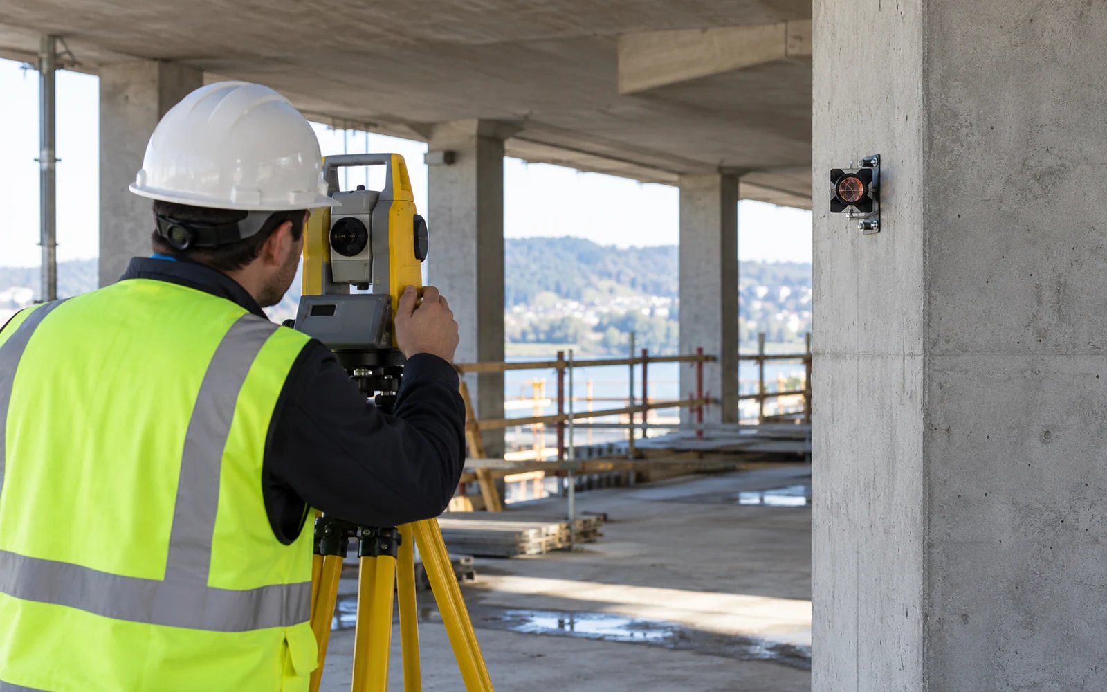
Keep angle, inferred displacement and survey checks separate
Store the observed angle change alongside any derived displacement, with the model version and assumptions. Mark a model-derived quantity as inferred rather than presenting it as a directly measured coordinate.
A chain of tilt measurements is also different from a single surface tiltmeter. The GEOKON 6300 manual uses known segment lengths and inclination changes to build a displacement profile. That calculation depends on the segment geometry and reference, not on multiplying one local angle by the full depth.
For downhole records, the inclinometer baseline guide addresses repeatability and reference surveys. For surface structures, choose independent optical, GNSS or displacement observations that can evaluate the specific translation or rotation being inferred.
Include uncertainty in the interpretation. Sensor precision, calibration, attachment stability, lever-arm uncertainty and model adequacy are different contributions. Extra decimal places in the conversion cannot remove an unknown pivot or an invalid rigidity assumption.
Use the result within the monitoring model
Do not derive structural safety thresholds from the illustrative 3.49 mm calculation. The responsible asset-monitoring design must connect the measured quantity to the behavior and decisions that matter.
In a bridge monitoring architecture, local tilt can complement other measurements without pretending to replace them. The same principle applies when selecting deformation-monitoring equipment for critical infrastructure.
Keep the installation geometry, axis convention, calibration and transformation with the reported displacement. A later calculation should be traceable back to the angle and geometric assumptions that produced it.
FAQs
Can a single tiltmeter detect pure translation?
Not by orientation alone. A structure can translate while keeping the same orientation. A tilt sensor may therefore show little change even though the structure has moved; an appropriate coordinate or displacement measurement is needed.
How can tilt be converted to horizontal displacement?
For a rigid segment of known fixed length L rotating about a fixed pivot, horizontal change is L times the difference between the sines of its current and baseline angles from vertical. Other geometries require different models.
Is displacement always length times the change in angle?
Only as a suitable small-angle approximation with angles in radians and the relevant geometry. It is not generally valid for a flexible structure, a moving pivot or an unknown lever arm.