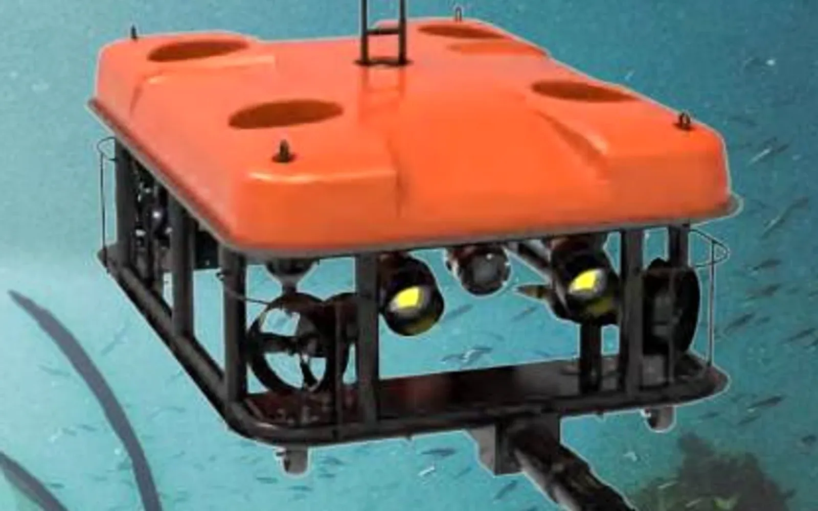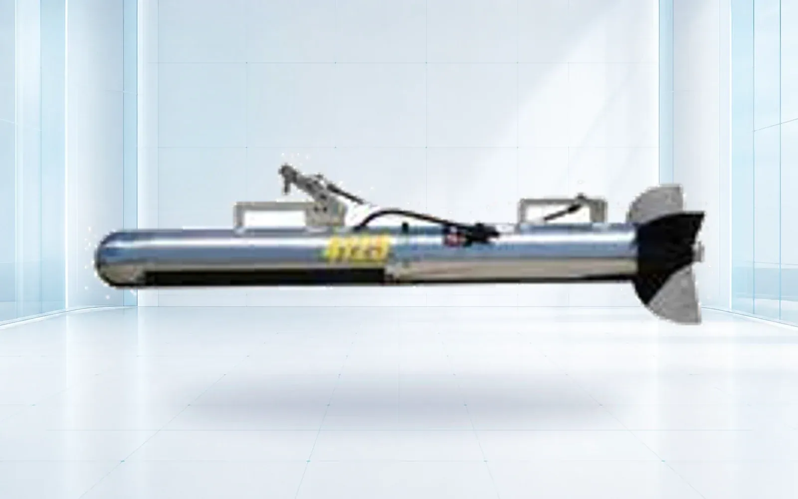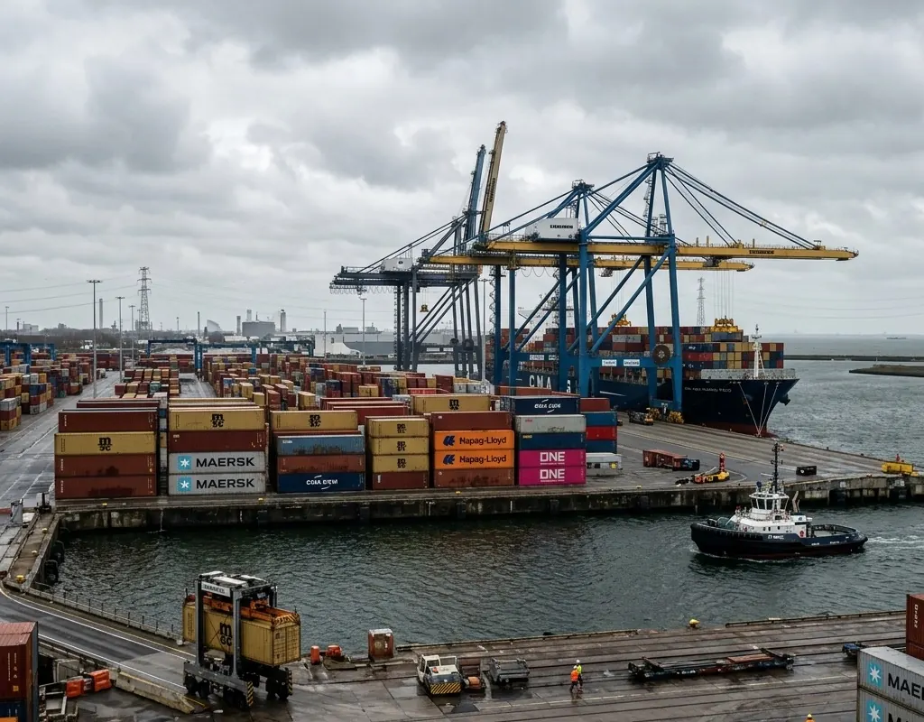
An effective and defensible port underwater inspection plan relies on building a continuous, repeatable evidence chain, not just evaluating individual sensor specifications. Broad, wide-area side scan sonar port inspection provides the crucial initial anomaly detection, which must then transition seamlessly into highly targeted ROV quay wall inspection for final confirmation. Strategically choosing the right underwater port security ROV means perfectly matching vehicle maneuverability and specialized sensor geometry to the specific operational task. This holistic workflow ensures that every identified target can be reliably reacquired by subsequent dive teams without wasting critical time.
Table of Contents
- 1. Mission Strategy and Planning
- 1.1. Divide the mission into evidence stages
- 1.2. Positioning is the bridge between sensors
- 2. Operational Execution
- 2.1. Conduct a system shakedown
- 2.2. Make findings repeatable
- 3. Commissioning and Quality Control
- 3.1. Establish survey control before launching
- 3.2. Match the platform to each stage
- 3.3. Accept an inspection capability, not a collection of devices
- 4. FAQs
1. Mission Strategy and Planning
1.1. Divide the mission into evidence stages
Side-scan sonar, imaging sonar and an ROV do not compete for one role. A side-scan system can search a wider corridor. Positioning and reacquisition move the team back to a target. Imaging sonar supports close awareness in poor visibility. The ROV captures visual or acoustic detail and may carry a tool.
The underwater ROV and sonar selection guide explains these tool differences. A port plan should connect them in one route and file structure.
| Stage | Primary output | Go/no-go question |
|---|---|---|
| Search design | Track lines, coverage and exclusion zones | Can the team cover the required asset safely? |
| Broad search | Georeferenced anomalies and coverage record | Is the target distinct enough for follow-up? |
| Reacquisition | Confirmed target position and approach | Can the ROV or close sonar return to it? |
| Close inspection | Video, acoustic imagery and measurements | Is the evidence sufficient for the asset decision? |
| Reporting | Finding, confidence, location and configuration | Can another crew repeat the inspection? |
1.2. Positioning is the bridge between sensors
A target coordinate needs an uncertainty, reference system and time. Towfish offset, vessel motion, acoustic positioning and current all affect where an anomaly is reported. Define how coordinates are passed from search software to the ROV team and how the final target position is corrected.
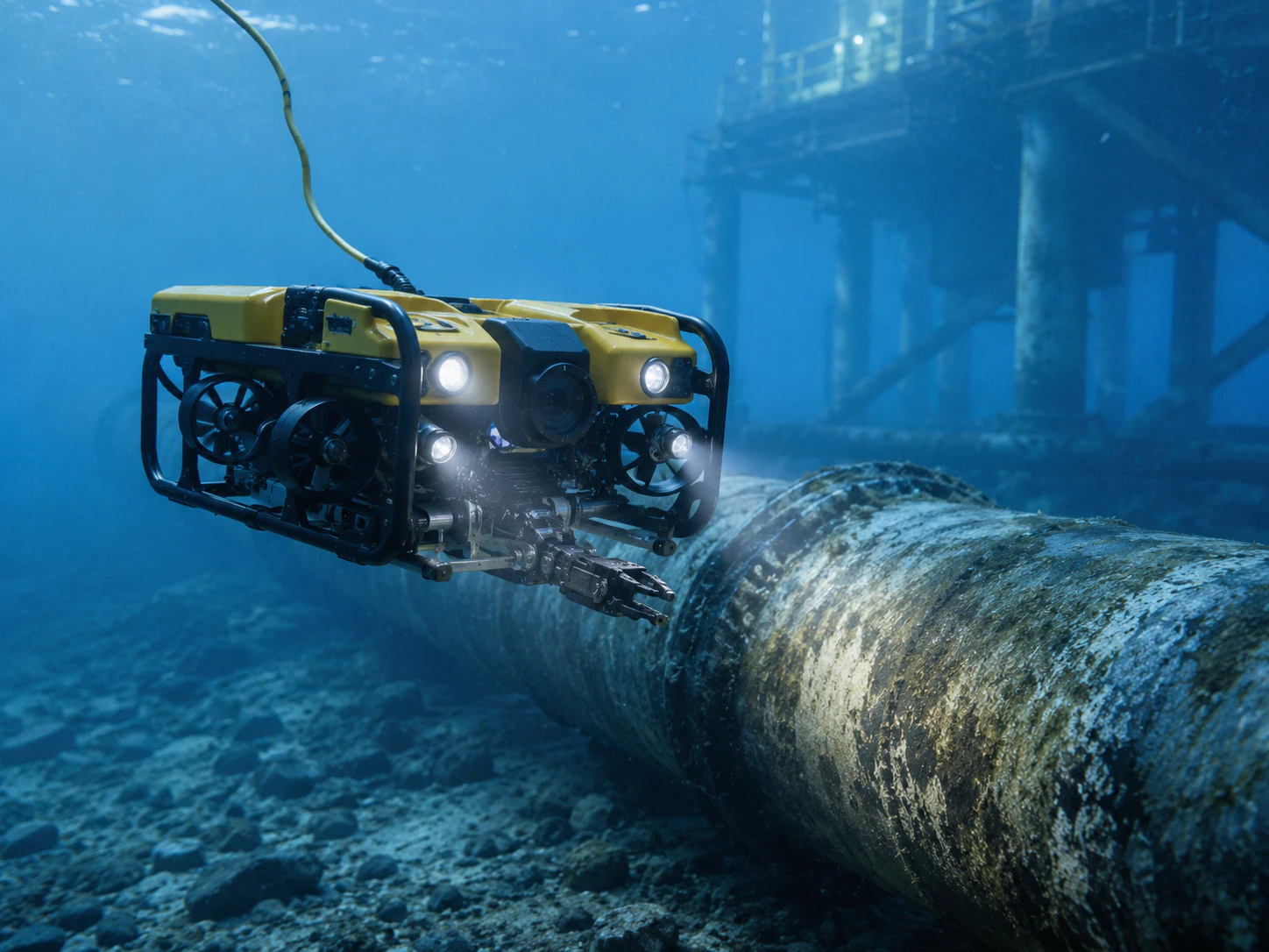
NOAA’s description of ROV operations highlights the tether as both the command-and-data path and a physical part of the system. Around quays, piles, chains and active vessels, tether geometry can be the limiting factor even when vehicle depth and thrust appear sufficient.
The ROV umbilical and tether management guide develops this constraint into a cable specification, documented load path and launch-to-recovery plan. It also separates a communications tether from an assembly explicitly rated for lifting.
2. Operational Execution
2.1. Conduct a system shakedown
A bench test cannot reproduce launch, deck handling, communications, piloting, positioning, sonar interpretation and evidence transfer. Run a shakedown with representative water, a known target and the actual crew.
Test camera and sonar recording, time synchronization, file naming, target marking, network loss, recovery and a second pass. NOAA uses shakedown operations to verify mission systems and train teams before production work; the same principle scales to a commercial port inspection.
2.2. Make findings repeatable
Every reported finding should identify the asset, location, inspection route, conditions, sensor configuration, operator, raw file and interpreted result. Separate direct observation from interpretation and state uncertainty where it affects action.
The port and water security architecture connects underwater evidence to surface and facility operations. For bridge, intake or dam work, use the critical infrastructure protection architecture as the parent workflow. Supporting records and source-review practices are available in the knowledge hub.
3. Commissioning and Quality Control
3.1. Establish survey control before launching
Agree the horizontal and vertical reference, time source, asset naming and coordinate format before collecting data. Mark quay faces, piles, chains, intakes and exclusion areas on the same working plan used by the vessel or ROV crew. If positioning quality varies by part of the site, record the expected uncertainty rather than treating every plotted point as equally precise.
The inspection data structure should be designed at the same time. A practical hierarchy connects mission, run, sensor file, target or finding, interpretation and follow-up action. File names should remain unique without depending on an operator’s memory. Raw sonar, navigation, video, still images and notes should share timestamps and identifiers.
| Control item | Minimum record | Reason |
|---|---|---|
| Position reference | Datum, coordinate system and method | Allows findings to be relocated |
| Time | Source, timezone and synchronization check | Correlates vehicle, sonar and video |
| Asset index | Stable asset and segment identifiers | Connects evidence to maintenance records |
| Sensor baseline | Model, settings, offsets and software version | Makes interpretation reviewable |
| Coverage log | Planned and completed lines or surfaces | Shows what was and was not inspected |
3.2. Match the platform to each stage
Broad search rewards stable coverage and positioning. Close inspection rewards maneuverability, stand-off control and useful camera or imaging-sonar geometry. Intervention adds tooling, reaction loads and a more demanding tether and launch system. One platform may support several stages, but the plan should not force it to perform a task for which its evidence is weak.
Define the handoff before mobilization. A side-scan anomaly should carry a position, dimensions, confidence and image into the reacquisition plan. An ROV finding should refer back to the search target and asset segment. If the close-look crew receives only a screenshot and an approximate verbal location, valuable survey time is lost.
3.3. Accept an inspection capability, not a collection of devices
Commissioning should prove launch and recovery, positioning, target marking, sonar and video recording, repeat approach, file transfer and report creation. Include a known target, a cluttered area and a second crew member attempting to relocate a finding from the first record. That last step is a strong test of whether the evidence is operationally reusable.
For recurring inspections, preserve comparable routes, viewpoints, sonar settings and environmental notes. Changes in current, visibility, vessel activity and biofouling can alter the result even when the asset is unchanged. A trend claim should therefore show both the observed difference and the conditions under which each dataset was collected.
4. FAQs
Why use both side-scan sonar and an ROV in a port inspection?
Side-scan sonar searches broad corridors efficiently, while positioning and reacquisition bring the team back to an anomaly so imaging sonar or an ROV can collect close, decision-ready evidence.
Why is positioning critical to underwater inspection evidence?
A finding is reusable only when another crew can relocate it. Record the coordinate system, time, method, uncertainty, vehicle or towfish offset and the link between search and close-inspection files.
What should commissioning prove for a port inspection system?
Commissioning should prove launch and recovery, positioning, target marking, repeat approach, sonar and video capture, file transfer and reporting with the actual crew under representative conditions.