An ROV's advertised cable length is not its usable working radius. Current, cable drag, bends, terminations, obstacles and the recovery arrangement can become limiting first. Specify the umbilical and tether as parts of a complete system, with a named load path, inspection record and approved route from launch to recovery.
Table of Contents
- 1. Draw Every Cable Segment and Load Path
- 2. Write a Cable Specification That Fits the Mission
- 2.1. Assign interface ownership
- 3. Current and Geometry Can Limit Reach Before Length Does
- 4. Make Launch and Recovery Part of the Design
- 5. Track Damage Across the Cable Lifecycle
- 6. Prove the Full Route During Mobilisation
- 7. FAQs
1. Draw Every Cable Segment and Load Path
Start with a system drawing. Show the surface power and control unit, reel or winch, deck leads, overboarding point, launch-and-recovery arrangement, any tether-management system and the ROV. Identify the function of every connection.
The words “tether” and “umbilical” are not enough to define a design. Different suppliers use them differently. For each segment, state whether it carries power, data, optical signals, mechanical loads or a combination. Identify the component responsible for taking load at each transition.
A cable that communicates with the vehicle is not automatically a lifting member. A lifting-rated arrangement includes the cable construction, terminations, handling equipment and approved method. If the supplier cannot identify that complete load path, do not treat the cable as an alternative recovery line.
The IMCA guidance on armoured umbilical lifecycle management covers procurement, installation, inspection, maintenance and discard criteria. Its public revision history includes an April 2024 update. The full applicable guidance and OEM documentation, not an abbreviated web checklist, should inform the operating procedure.
2. Write a Cable Specification That Fits the Mission
Depth rating is only one input. Specify the required power and data interfaces, connector arrangement, deployed length, buoyancy characteristics, environmental exposure and compatibility with the handling system.
Request the manufacturer’s permitted tension, bend limits, termination requirements and inspection criteria for the actual assembly. Check that these apply to the installed configuration and intended duty, rather than to a similar cable sold for another application.
The electrical and optical design also matters. A mechanically suitable cable may still introduce unacceptable power losses, communication problems or connector limitations. Confirm the complete path under representative loading and data traffic rather than testing an unloaded cable on a workshop bench.
2.1. Assign interface ownership
Name who approves the cable-to-vehicle connection, the reel or winch interface, the overboarding geometry and any modifications. These boundaries are common places for assumptions to survive until mobilisation.
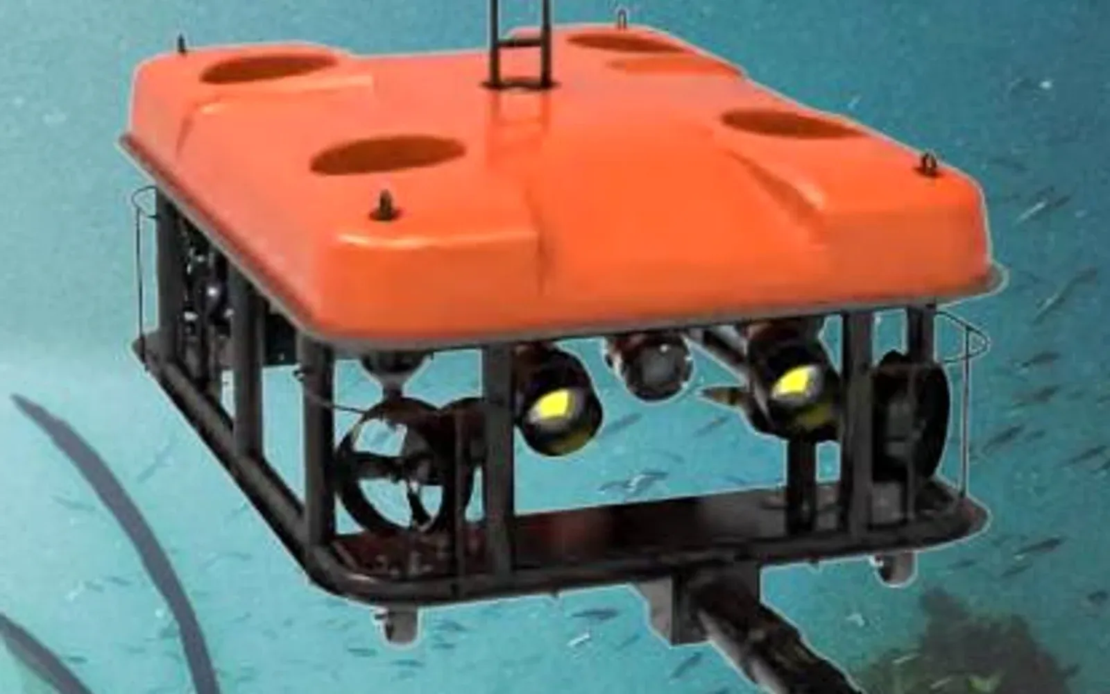
For the G70 observation and light-work ROV, request the supplied tether, surface equipment and recovery documentation together. Adding a payload such as an imaging sonar also calls for a power, data and mechanical-integration review; the vehicle name alone does not establish compatibility.
3. Current and Geometry Can Limit Reach Before Length Does
A cable does not follow the straight line drawn on a map. It curves in the water, responds to current and may contact the vessel, seabed or structure. That deployed shape affects both drag and the ability to recover the vehicle.
Assess the route at the relevant depths and water conditions. A sheltered surface observation does not necessarily describe conditions beside a submerged structure. Changes in vessel position or cable deployment can alter the load even when the ROV remains near the same point.
Define the operating envelope through the approved engineering and trial process. Do not extrapolate a maximum-current claim to every combination of cable length, payload and direction of travel. The ability to reach a location is not the same as the ability to work there while retaining a controlled return path.
Plan around snag and abrasion risks. Pilings, edges, protrusions and moving marine equipment should be considered in the route and exclusion arrangements. Where the route cannot be managed, change the launch position, method or scope rather than assuming that more thrust solves the problem.
4. Make Launch and Recovery Part of the Design
Recovery is not simply launch in reverse. Equipment condition, visibility, vessel motion, load transfer and the state of a latch or termination can determine whether the final part of the operation is controlled.
An IMCA safety flash describing an ROV dropped to the seabed reports an incident involving a tether-management system, a launch-and-recovery latch and damage to the umbilical. The report identifies maintenance and installation-specific procedure issues. It is an industry incident, not an OMNI case study.
The procurement lesson is to evaluate the interfaces as a system. Require the correct maintenance plan, visibility of relevant status indications, defined roles and the procedure for that installation. Personnel should be kept clear of hazardous load paths under the approved work plan.
Plan the response to loss of power, communications or normal recovery capability before deployment. The appropriate response depends on the equipment and site; it should not be improvised by pulling harder on an uncertain cable or sending personnel into an unplanned recovery operation.
5. Track Damage Across the Cable Lifecycle
A useful inspection record follows the assembly, including its terminations and any permitted retermination or repair. Preserve the serial identity, configuration, inspections, load events, observed damage and resulting decisions.
| Stage | Main concern | Evidence required |
|---|---|---|
| Procurement | Cable or termination unsuitable for duty | Assembly specification, ratings and interface approval |
| Installation | Excessive bending, poor routing or incompatible handling | Installation inspection and approved geometry |
| Mobilisation | Wrong configuration or incomplete maintenance | Equipment identity, checks and current records |
| Operation | Abrasion, snagging, abnormal tension or damaged connections | Operator observations and event log |
| Recovery | Uncontrolled load transfer or handling-system fault | Installation-specific procedure and functional checks |
| Storage and return to service | Hidden damage or loss of history | Inspection, storage record and release decision |
Do not define a generic discard limit from appearance alone. Use the applicable manufacturer’s criteria and competent inspection process. An undamaged-looking outer surface does not establish the condition of every internal element or termination.
Quarantine suspect equipment within the site’s maintenance system until the responsible person determines its status. Keep the reason for that decision with the asset so a different shift does not unknowingly return it to service.
6. Prove the Full Route During Mobilisation
A mobilisation check should demonstrate the intended combination of surface equipment, vehicle, payload and cable arrangement. Test communications and video, verify the relevant state indications and review how the team will identify and respond to faults.
The field trial should represent the work route and recovery conditions within the approved safety envelope. Record which limits were demonstrated and which remain untested. A successful short deployment next to the launch point should not become evidence for a substantially different route.
Agree on deliverables before the job: configuration drawing, applicable operating limits, inspection record, maintenance responsibilities, spares and the approved contingency plan. Those records are often more useful for ongoing operation than another maximum-depth headline.
The port underwater inspection plan addresses search, reacquisition and close inspection. Cable management supports that evidence chain by making the route repeatable and recoverable. The underwater systems category and port and water solution provide the broader system context.
Keep the product catalog beside the project-specific equipment schedule. For a configuration review, send OMNI UXV the depth, current information, structure geometry, launch arrangement and required payloads.
7. FAQs
What is the difference between an ROV tether and an umbilical?
Terminology varies by system. An umbilical often connects the surface system to the vehicle or tether-management system, while a tether may connect the management system to the vehicle. Confirm the actual segments and functions rather than assuming that a name establishes a load rating.
Can the communications tether be used to lift an ROV?
Only when the complete cable, termination and handling arrangement is explicitly designed and rated for the intended lifting duty. Do not infer a safe lifting capability from cable diameter, armor or the fact that the cable is attached to the vehicle.
Why can an ROV have less working reach than its cable length?
The deployed cable must follow a three-dimensional path and may carry current-induced drag, slack and loads around structures. Vehicle thrust, routing, abrasion and recovery constraints can limit the operation before all the cable is paid out.
When should an ROV umbilical be replaced?
Use the manufacturer's discard criteria and the applicable inspection and lifecycle-management program. Damage history, terminations, load events and inspection findings matter; there is no defensible universal replacement interval for every cable and duty.