An ROV sonar inspection becomes useful engineering evidence only when the team can explain where it searched, how a contact was created, how the target was reacquired, what sonar geometry and settings applied, what visual or contact confirmation followed, and which areas remain unresolved.
Table of Contents
- 1. Define the Question and the Inspection Zones
- 2. Shakedown the Complete Vehicle and Sonar Chain
- 3. Run a Search Pattern That Can Be Reconstructed
- 4. Create and Reacquire Contacts Deliberately
- 5. Hand Off From Acoustic Context to Close Inspection
- 6. Reconcile Coverage and Deliver an Auditable Record
- 7. FAQs
1. Define the Question and the Inspection Zones
State the decision for each asset zone: find obstructions, screen for geometry change, locate a known feature, identify a path for close visual inspection, verify clearance, or create a repeatable baseline. Sonar cannot answer an unspecified question merely because it records the whole dive.
Divide the asset into stable zones with drawings or a field-derived coordinate convention. Record water depth, current, turbidity, expected geometry, launch access, tether hazards, acoustic shadow, reflective surfaces, required resolution, positioning method, and the next method if the result is inconclusive.
NOAA explains that side-scan sonar primarily creates seafloor imagery while multibeam systems measure swaths of depth. An ROV-mounted imaging sonar has another geometry again. Specify the instrument and output required instead of using “sonar” as a generic deliverable.
2. Shakedown the Complete Vehicle and Sonar Chain
Inspect the vehicle, tether, sonar mount, connectors, camera, lights, depth and heading sensors, altimeter, navigation, recorder, topside display, power, storage, and time. Confirm the sonar field is clear of the ROV frame, bubbles, tether, manipulators, and moving appendages.
Use a known target to test range, bearing, gain or other approved settings, image orientation, mounting offset, scale, recording, and export. If vehicle positioning is required, verify its coordinate frame and uncertainty. NOAA’s 2026 ROV shakedown describes calibrating USBL positioning and checking sensors, cameras, and other systems before operational dives; the same systems discipline applies at a smaller scale.
3. Run a Search Pattern That Can Be Reconstructed
Choose tracks and headings that expose the relevant surfaces while controlling acoustic shadow and tether risk. Record planned line, actual path, speed, altitude or standoff, sonar range, field of view, update setting, heading, depth, and deviations. A sweep that looks complete on the operator display may contain masked areas behind structural members.
| Search record | Why retain it | Quality check |
|---|---|---|
| Track and vehicle state | Reconstructs where the sonar looked | Compare actual path with zone plan |
| Sonar range and settings | Explains resolution and appearance | Freeze or log every change |
| Heading and mount offset | Converts display bearing to scene direction | Verify against a known feature |
| Environmental state | Explains visibility, current and vehicle motion | Log changes by zone |
| Coverage exception | Prevents silence from implying completion | Assign disposition and rework owner |
The 2026 NOAA Hydrographic Survey Specifications and Deliverables provide a strong model for retaining uncertainty, coverage, feature, metadata, and raw-data context. An asset inspection will use tailored criteria, but it needs the same traceability.
4. Create and Reacquire Contacts Deliberately
When a potential target appears, assign an ID before leaving the search view. Save a clip or raw segment with time, range, bearing, settings, image orientation, target shadow, surrounding structure, vehicle pose, and uncertainty. Distinguish a contact from an interpreted finding.
Plan the return path using stable geometry, not memory. Approach from the same heading and range, then vary one dimension at a time to understand the target. A feature that changes or disappears with angle may be an acoustic artifact, shadow edge, or ambiguous geometry. Preserve unsuccessful reacquisition attempts.
5. Hand Off From Acoustic Context to Close Inspection
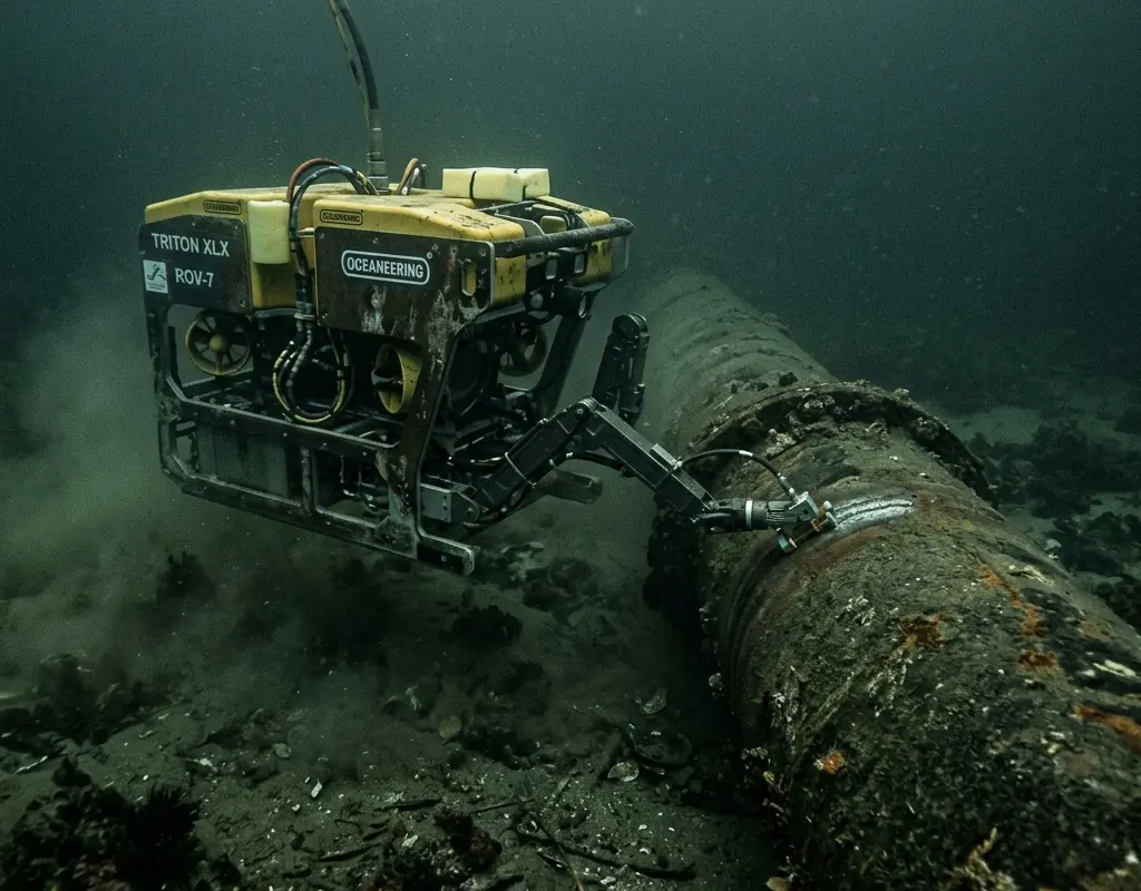
Use sonar to guide a controlled approach until camera, scale, laser, probe, cleaning tool, or other approved method can answer the engineering question. In poor visibility, a short-standoff camera view may show only a tiny portion of the scene; retain sonar context so reviewers know where the image belongs.
Do not convert a bright return or acoustic shadow directly into corrosion, cracking, scour, debris type, or structural severity. Record observable geometry and confidence, then route uncertain findings to the responsible inspector or engineer. The ROV camera guide for turbid water helps define the optical handoff.
6. Reconcile Coverage and Deliver an Auditable Record
At the end of each zone, confirm planned lines, usable sonar records, settings, navigation, contacts, reacquisition, close views, blind areas, and exceptions. Preserve originals and make annotations as linked derivatives. Keep the contact register synchronized with media filenames and the final finding list.
USACE underwater-inspection guidance notes that murky water can limit ROV optical effectiveness and places manned and unmanned underwater vehicles among available inspection methods. State what the ROV could not resolve and which alternate method is required.
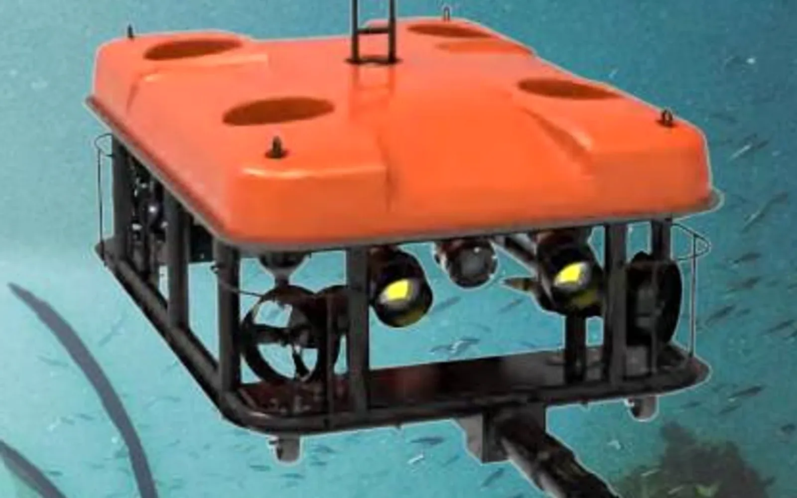
Review the SNR-C400 imaging sonar with the G70 ROV as candidate components to verify. The underwater systems category, port and water-security solution, and resource center can organize the zone plan, settings, contact log, and evidence package.
7. FAQs
What can imaging sonar add to an ROV inspection?
Imaging sonar can support navigation, structure recognition, obstacle detection, target search, standoff control, and reacquisition when optical visibility is poor, provided settings and geometry are retained.
Can an ROV sonar image identify a structural defect by itself?
Not reliably in every case. Acoustic imagery shows return strength, geometry, and shadow shaped by viewpoint and settings; material, dimensions, and severity may require close visual, contact, survey, or engineering confirmation.
How should an ROV sonar contact be recorded?
Assign a stable contact ID and preserve time, range, bearing, sonar settings, vehicle position and heading, depth, target context, image clip, uncertainty, reacquisition route, confirmation, and disposition.
What proves that an ROV sonar inspection achieved coverage?
A planned track and zone register reconciled with navigation, sonar records, contact logs, quality checks, exceptions, blind areas, and explicit missed or unusable sections provides stronger proof than recording duration.