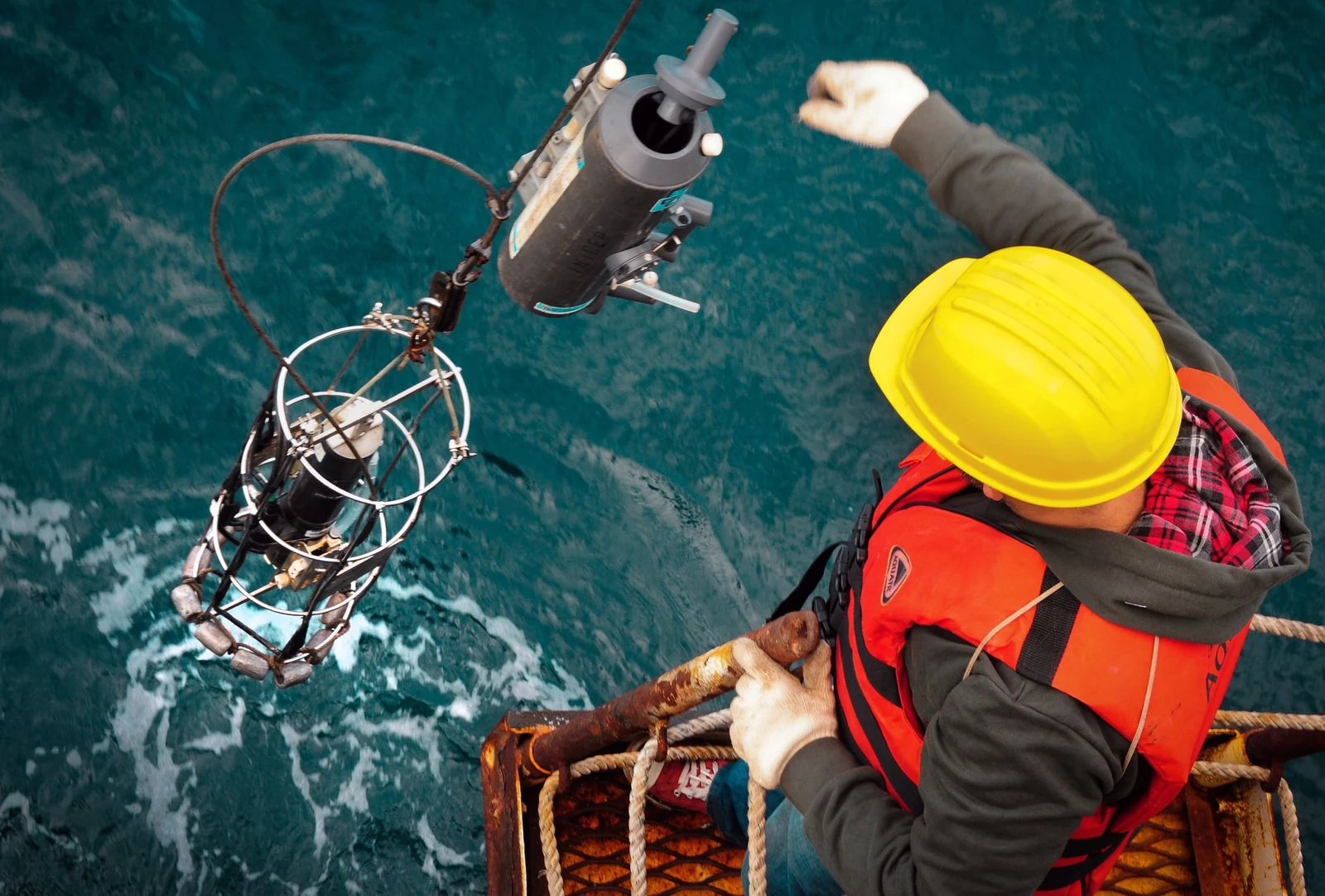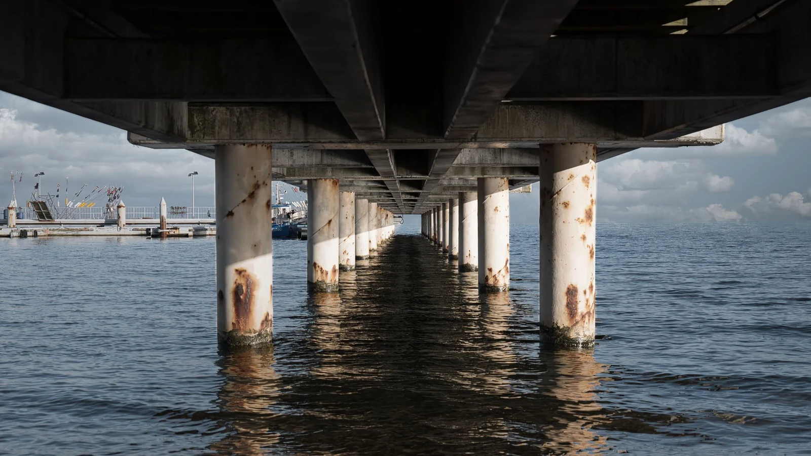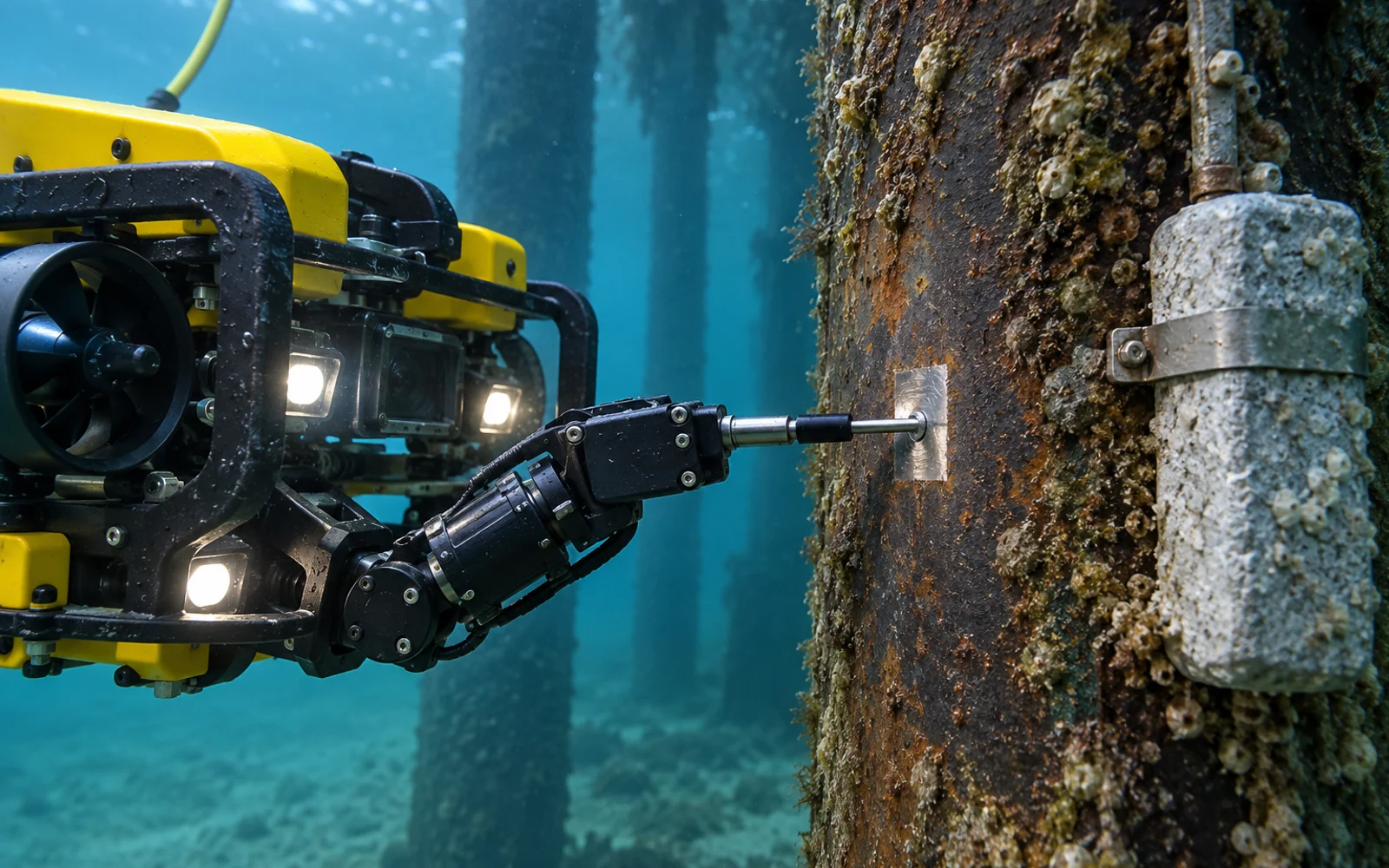
An ROV can carry a probe to measure electrical potential at a submerged structure. Interpretation requires a known reference electrode, a defined measurement circuit and reliable contact. Link each reading with its asset location, instrument checks and measurement conditions.
Table of Contents
What does an ROV CP survey measure?
A cathodic-protection survey measures electrical potential using a specified reference electrode and measurement arrangement. It complements visual inspection of coatings, anodes and exposed metal. It does not directly measure remaining wall thickness or prove the cause of corrosion.
For example, EDT describes a silver/silver-chloride reference electrode used with submerged structures and sacrificial anodes. That product description illustrates the importance of the reference and circuit; it does not establish that the electrode is suitable for every ROV, depth or inspection contract.
Select the instrument, probe, cables and integration for the actual water, depth and task. Confirm the method and interpretation basis with the responsible corrosion engineer before collecting measurements.
Why must the reference electrode be named?
A potential is a difference between two points. Without the reference electrode, polarity convention and measurement circuit, an isolated voltage value can be misleading.
Record electrode type, identifier, condition and the manufacturer’s specified checks. Preserve calibration or verification records available for the instrument. Include water characteristics required by the method and any temperature compensation or correction applied.
Never silently compare values taken with different reference systems. If a conversion is appropriate, retain the original value, conversion basis and converted value separately. A report should allow the reviewer to reconstruct which quantity was actually measured.
Design the reading record around the asset
Before the dive, assign measurement locations using stable structural IDs. A coordinate alone can be inadequate around repetitive piles, members or pipeline supports.
| Required field | Evidence collected | Why an empty field matters |
|---|---|---|
| Asset and location ID | Drawing reference plus video context | The reading cannot be revisited reliably |
| Reference and polarity | Electrode type and circuit convention | Values may not be comparable |
| Instrument verification | Before/after checks under the method | Drift or damage may go unnoticed |
| Probe contact or stand-off | Close-view clip and operator note | The intended measurement may not have occurred |
| Potential and units | Original record and stable interval | A transient may be mistaken for a settled result |
| Exceptions | Access, coating or contact limitation | A skipped point may look like coverage |
This is a measurement-traceability template, not a universal CP acceptance table. Material-specific limits belong in the approved inspection specification.
How can the crew distinguish a reading from a transient?
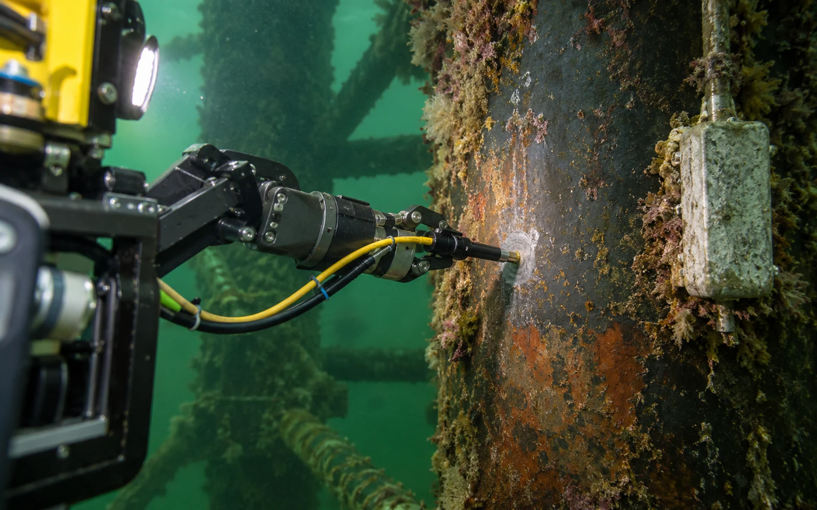
Observe the signal while documenting the probe position and contact condition required by the selected method. Retain the time series or stable interval where available, rather than selecting a favorable single frame.
An erratic trace can arise from poor contact, motion, cable problems or other measurement conditions. Record the observation, repeat according to the procedure and preserve unsuccessful attempts. Do not remove a coating or force a probe into a structure without authorization in the inspection method.
The camera should show where the tool is located and whether contact was maintained. Positioning should be accurate enough to return to the same structural feature. The USBL positioning guide explains why vehicle coordinates and a probe contact location are not automatically identical.
Combine electrical and visual evidence carefully
A depleted-looking anode and an unexpected potential can inform an engineering review, but neither should become an unsupported diagnosis in the operator log. Keep observed condition, measured value and engineering interpretation in separate fields.
For pipeline work, link the CP point to the relevant segment and any coating or support observation. The underwater pipeline inspection workflow provides the broader coverage structure.
The inspection package should connect each potential measurement with the probe, reference electrode, contact condition and asset location. Retain exceptions and instrument checks alongside the readings.
When the integrity question concerns remaining wall thickness, use a separately specified ROV ultrasonic thickness measurement workflow with probe contact, material settings and located readings.
FAQs
Can an ROV camera alone verify cathodic protection?
No. Visual evidence can document anodes and surface condition, but an electrical potential survey requires appropriate measurement equipment and a defined method.
Is one potential threshold valid for every submerged structure?
No. Interpretation depends on material, environment, reference electrode and the applicable inspection method. The asset engineer must define the acceptance basis.
What must accompany a potential reading?
Retain location, time, units, polarity, reference-electrode type, instrument checks, contact evidence and any stability or access limitations.