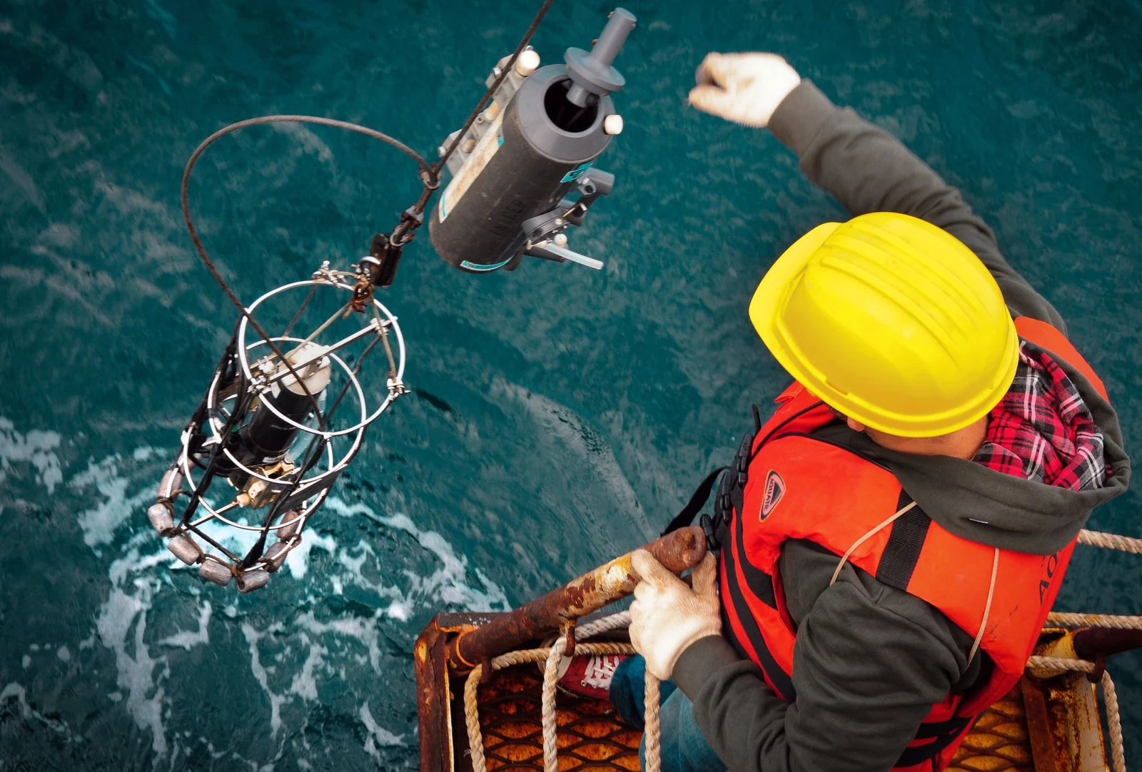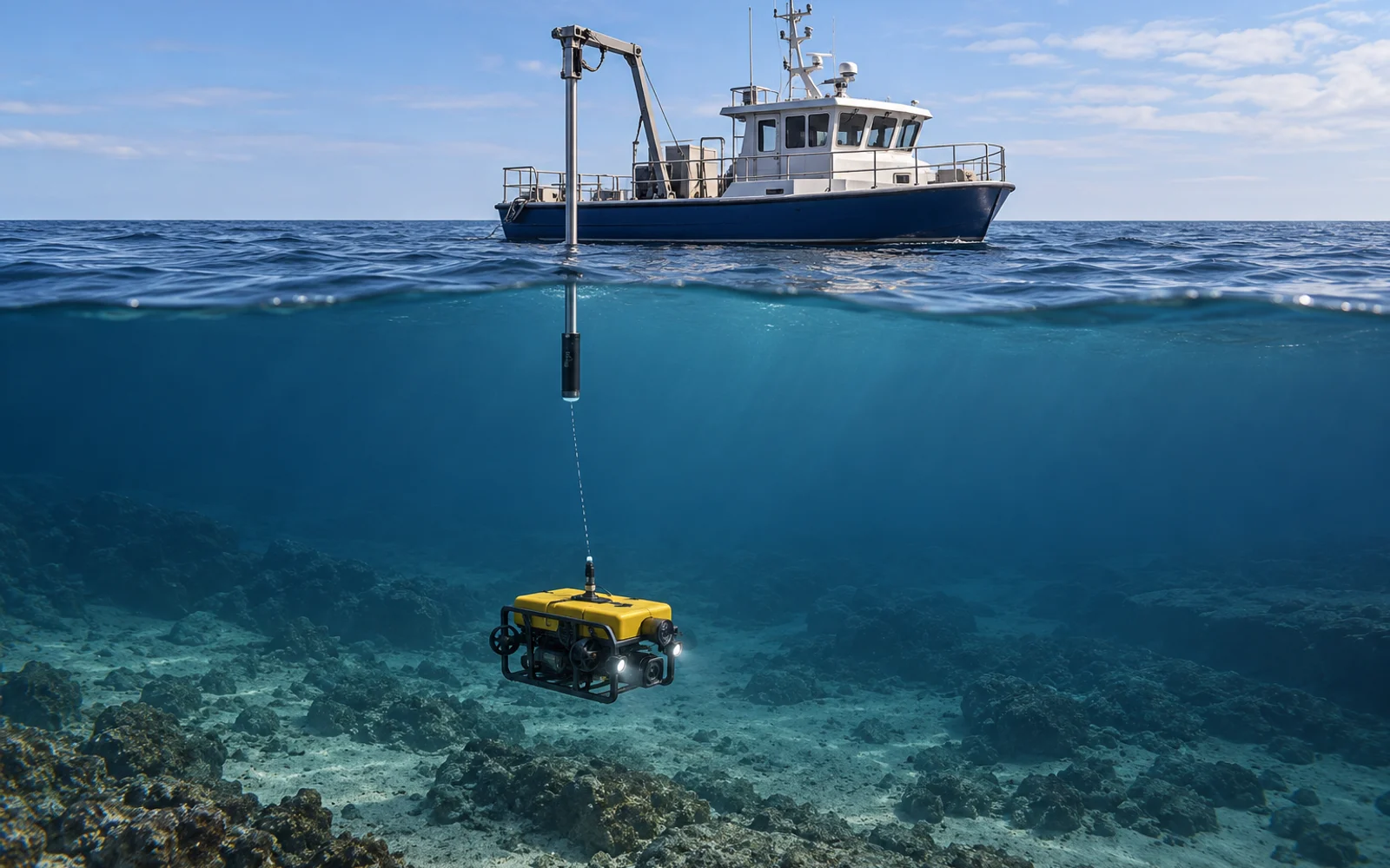
USBL positioning turns acoustic travel time and direction into an underwater location relative to a surface reference. The resulting map position depends on much more than the acoustic transceiver. Vessel position, attitude, mounting offsets, sound speed and timestamps all belong in the error budget.
Table of Contents
How does USBL locate an ROV?
An ultra-short baseline system measures acoustic direction and travel time between a compact receiving array and an underwater unit. Those observations establish a relative position. Converting it to project coordinates requires a correctly positioned and oriented surface reference.
Advanced Navigation explains the range-and-bearing principle. Its product-specific update rates or performance claims should not be generalized to another USBL installation.
For an inspection, distinguish vessel position, transceiver position, ROV transponder position and the location of the observed defect. They are four different points. A detailed sonar image does not eliminate the transformations between them.
Build an error budget before quoting accuracy
Separate systematic errors from variable noise. Averaging may reduce some random scatter while leaving an incorrect mounting offset almost unchanged.
For small angular errors, transverse error is approximately range × angle in radians. As an illustrative calculation, a 0.5-degree angular error at 100 m gives about 0.87 m of transverse error. At 300 m it gives about 2.62 m. This is a geometric sensitivity example, not a prediction for any product.
| Contribution | What to document | Useful verification |
|---|---|---|
| Surface position | Reference system and GNSS quality | Known reference or independent solution |
| Heading and attitude | Sensor source, alignment and latency | Controlled orientations and calibration |
| Lever arms | Transceiver-to-reference offsets | Measured installation drawing |
| Acoustic travel path | Sound-speed information and multipath context | Representative profile and geometry checks |
| Time alignment | Observation time versus receipt time | Common-event or logged timing test |
| Target offset | Transponder, camera and target geometry | Known feature with recorded standoff |
Do not simply add every quoted manufacturer accuracy figure. Determine whether figures are bounds, standard deviations, percentages of slant range or results under specific test conditions. Root-sum-square combination requires defensible assumptions about independence and statistical meaning.
Why does calibration need a verification run?
Calibration estimates corrections within its chosen model. Verification checks whether those corrections work on observations outside the calibration fit.
Sonardyne’s calibration guidance emphasizes heading quality, installation offsets, sound velocity and verification. It also explains why a moving calibration beacon compromises the reference. These are useful considerations when reviewing a supplier’s method.
Record which parameters were adjusted, the geometry sampled and the observations withheld for checking. If all evidence comes from the same fitted run, request an independent repeat before accepting the coordinate chain.
What changes near structures?
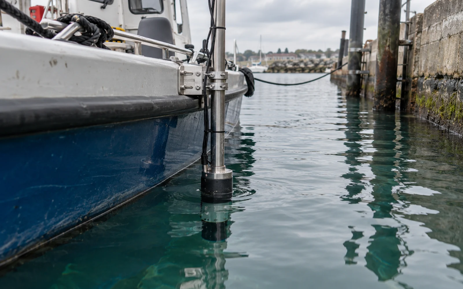
Quay walls, hulls and confined water can obstruct direct acoustic paths or generate reflections. Surface motion can also move a pole-mounted transceiver. A smooth output trace may reflect filtering rather than good raw observations.
Review quality flags, rejected observations and residuals alongside the position. Compare different headings and stand-off geometries. If a region cannot support dependable positioning, define another localization method or record a larger uncertainty rather than drawing a precise-looking point.
Combine USBL with DVL navigation only through a supported integration. Each sensor must retain its own reference, timestamps and validity; more sensors do not automatically produce a better result.
Deliver coordinates that support reacquisition
For every important contact, retain the coordinate reference, capture time, positioning quality, vehicle pose, sensor offsets and visual or sonar context. Distinguish the estimated target location from the transponder trajectory.
The port underwater inspection plan connects target identification with repeat visits. Include a representative localization trial, calibration record and error budget in the selected ROV’s handover.
FAQs
Why can USBL error grow with distance?
Angular uncertainty produces a larger transverse position error as range increases. Sound-speed, vessel-reference and installation errors can contribute as well.
Does a stable USBL track prove absolute accuracy?
No. A track can be repeatable while carrying a systematic heading, offset or reference-coordinate error. Independent verification is needed.
Can an ROV camera target use the transponder coordinates unchanged?
Only when that approximation meets the task's uncertainty requirement. Transponder-to-camera offsets and camera-to-target range may need to be included.